From idea to market-ready product, our NPI solutions make every stage easier, faster. Discover How We Help
Help Center

Views: 259 Author: Capital Technology Publish Time: 2026-08-07 Origin: Site
Content Menu
● Why Centrifugal Fan Balancing Matters
● Static vs. Dynamic Fan Balancing
>> Static Balancing for Simple Impellers
>> Dynamic Balancing for Industrial Fans
● Safety Checks Before Balancing a Centrifugal Fan
● Step-by-Step Static Balancing Procedure
>> 1. Clean and Inspect the Impeller
>> 2. Mount the Impeller on a Low-Friction Fixture
>> 4. Apply a Trial Correction
>> 5. Verify Neutral Rest Positions
● Step-by-Step Dynamic Balancing Procedure
>> 1. Establish a Baseline Vibration Reading
>> 2. Confirm the Mechanical Condition First
>> 3. Install a Secure Trial Weight
>> 4. Calculate and Install Permanent Correction
● How to Diagnose Imbalance vs. Other Fan Problems
● Preventive Maintenance That Keeps Fans Balanced
>> Recommended Maintenance Schedule
● Design Considerations for OEM Engineers
● Need a Reliable Fan Balancing Strategy?
● FAQ
>> 1. How often should a centrifugal fan be balanced?
>> 2. Can I balance a centrifugal fan without a vibration analyzer?
>> 3. Why is my fan still vibrating after balancing?
>> 4. Should I add weight or remove material when balancing a fan?
>> 5. What is the difference between one-plane and two-plane balancing?
>> 6. Does a balanced centrifugal fan use less energy?
A well-balanced centrifugal fan runs with lower vibration, less noise, and more stable airflow. In our work supporting DC fan, AC fan, blower, and thermal-management applications, we have seen that centrifugal fan balancing is not simply a factory process—it is a practical reliability measure that can protect bearings, motors, brackets, electronics, and the surrounding system.
This guide explains how to balance a centrifugal fan safely, when static balancing is sufficient, when dynamic balancing is necessary, and how maintenance teams can prevent imbalance from returning. It is written for OEM engineers, maintenance technicians, industrial equipment builders, and buyers specifying cooling fans for demanding applications.

Centrifugal fan imbalance occurs when the impeller's mass is not distributed evenly around its rotational axis. Even a small mass difference can create a substantial centrifugal force once the impeller reaches operating speed.
The result is often a familiar pattern: increased vibration, unusual noise, loose fasteners, premature bearing wear, and eventually unplanned downtime. In enclosed equipment such as telecom cabinets, power systems, automation equipment, and industrial control panels, vibration can also affect connectors, PCB assemblies, and sensitive electronic components.
A balanced fan helps deliver:
- Lower vibration transmitted to the housing and mounting structure
- Reduced mechanical noise and tonal noise
- Longer bearing, shaft, and motor life
- More stable airflow and cooling performance
- Lower risk of fatigue cracks in brackets, impellers, and welds
- Fewer service interruptions and replacement costs
Important: Balancing cannot solve every vibration problem. Misalignment, bearing damage, aerodynamic turbulence, loose foundations, belt issues, rubbing, and resonance can produce similar symptoms. Confirm the root cause before adding or removing material from an impeller.
Choosing the correct balancing method is the first technical decision. The wrong method can hide a problem instead of correcting it.
| Balancing method | Best for | Correction planes | Typical tools |
|---|---|---|---|
| Static balancing | Small, narrow, lower-speed impellers | One | Mandrel, low-friction rails, test weights |
| Dynamic balancing | Wider, higher-speed, industrial impellers | Two | Vibration analyzer, accelerometers, tachometer, balancing system |
| Field trim balancing | Installed fans with accessible correction points | One or two | Portable analyzer, trial weights, phase reference |
Static balancing corrects the heavy spot of a rotor in one plane. It is most useful when the impeller behaves like a relatively thin disc and the main issue is a single heavy area.
For example, a compact centrifugal blower wheel may be statically balanced before installation. If the wheel repeatedly rolls to the same position on a balancing mandrel, its center of mass is offset from the shaft axis.
Static balancing is practical, but it has a limitation: it cannot reliably correct couple imbalance. A fan can appear balanced when stationary but still vibrate at speed because its mass distribution differs from one side of the wheel to the other.
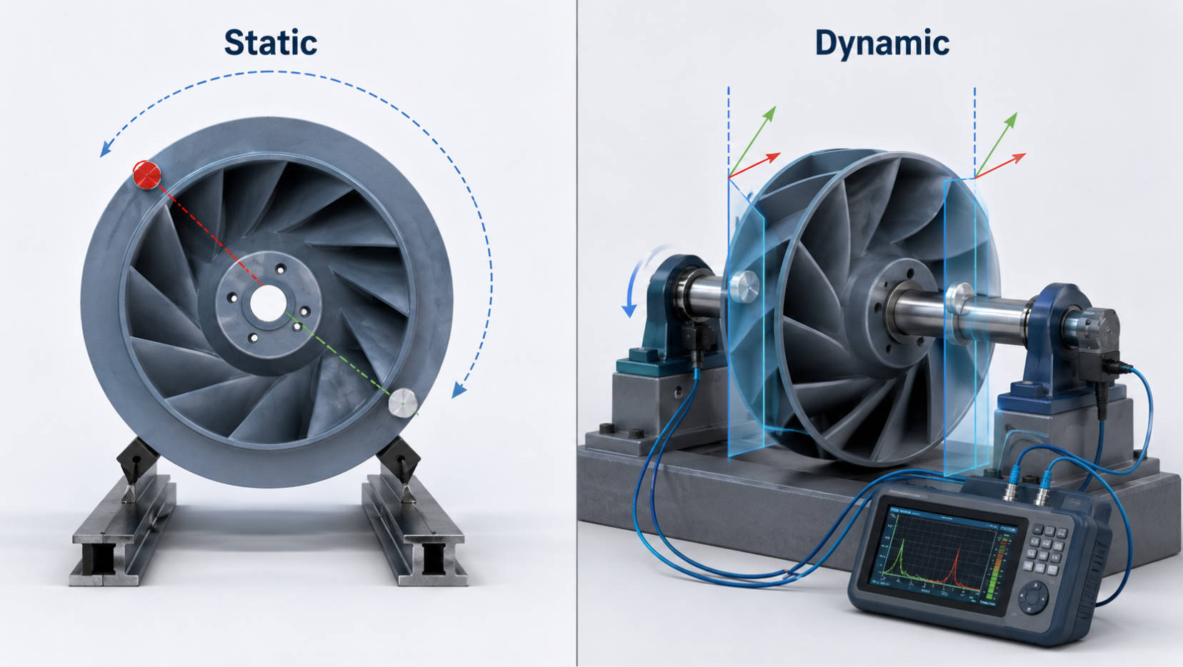
Dynamic balancing measures vibration while the fan rotates. It uses vibration amplitude and phase data to calculate the correction mass and its angular position.
This is usually the preferred method for:
- High-speed centrifugal fans
- Large backward-curved or forward-curved impellers
- Double-inlet and belt-driven fans
- Wide impellers with a significant axial width
- Fans used in industrial, telecom, medical, rail, and critical cooling applications
- Equipment that must meet documented vibration requirements
Expert insight: If an impeller has meaningful width, high rotational speed, or a strict reliability requirement, treat two-plane dynamic balancing as the safer engineering choice.
Never begin fan balancing while the machine can start unexpectedly. Rotating equipment stores energy, and an unsecured correction weight can become a serious projectile hazard.
Before inspection or adjustment:
1. Isolate electrical power using your site's lockout/tagout procedure
2. Verify that the impeller has completely stopped
3. Confirm that stored energy has been released
4. Wear appropriate PPE, including safety glasses, gloves, and protective footwear
5. Inspect guards, access doors, and mounting hardware
6. Check the impeller for cracks, corrosion, rubbing marks, bent blades, or missing fasteners
7. Record the fan model, operating speed, airflow condition, and existing vibration readings
Do not run a fan with temporary weights unless they are securely attached and the test is controlled by trained personnel. For high-speed or safety-critical equipment, use a qualified balancing specialist and follow the fan manufacturer's instructions.
Static balancing is suitable for detached, relatively small, and non-critical impellers. The wheel must be clean before testing; dust, oil, adhesive residue, or moisture can distort the result.
Remove dust, dirt, process deposits, loose paint, and foreign objects from the blades and backplate. Then inspect the hub, welds, blades, and keyways carefully.
Look for:
- Bent or damaged blades
- Cracked welds
- Uneven corrosion
- Missing balance clips or weights
- Build-up concentrated on one side
- Loose hub components
If structural damage is present, repair or replace the impeller before balancing. Balancing a cracked wheel may reduce vibration temporarily, but it does not restore mechanical integrity.
Place the impeller on a clean, level balancing mandrel, knife-edge rails, or roller fixture. The shaft or arbor must be straight and correctly fitted to the hub.
Allow the rotor to rotate freely. Avoid touching the wheel during the final movement because even a light contact can affect the result.
Let the impeller settle naturally. Mark the lowest point with a removable marker. Repeat the test several times, rotating the impeller to different starting positions.
If the same location repeatedly returns to the bottom, that area is the heavy spot. If the stopping position changes randomly, first check the fixture level, bearing friction, and impeller cleanliness.
Place a small trial weight opposite the heavy spot. If the heavy spot is at the 6 o'clock position, begin testing near the 12 o'clock position.
Add mass gradually. Avoid large correction weights because they can overcorrect the wheel or create a new imbalance.
Common correction methods include:
- Adding a welded balance tab or approved clip
- Adding a screw-on weight at a designed correction location
- Removing a small amount of material from the heavy side
- Grinding a designated balancing area, where approved by the manufacturer
Never remove material from a blade, hub, or structural weld unless the design specifically permits it.
The impeller is statically balanced when it can remain at multiple angular positions without consistently rotating back to one heavy point.
Test at least four positions around the wheel. Document the final correction location, correction mass, and correction radius. This record will be valuable if vibration returns after cleaning, repair, or service.
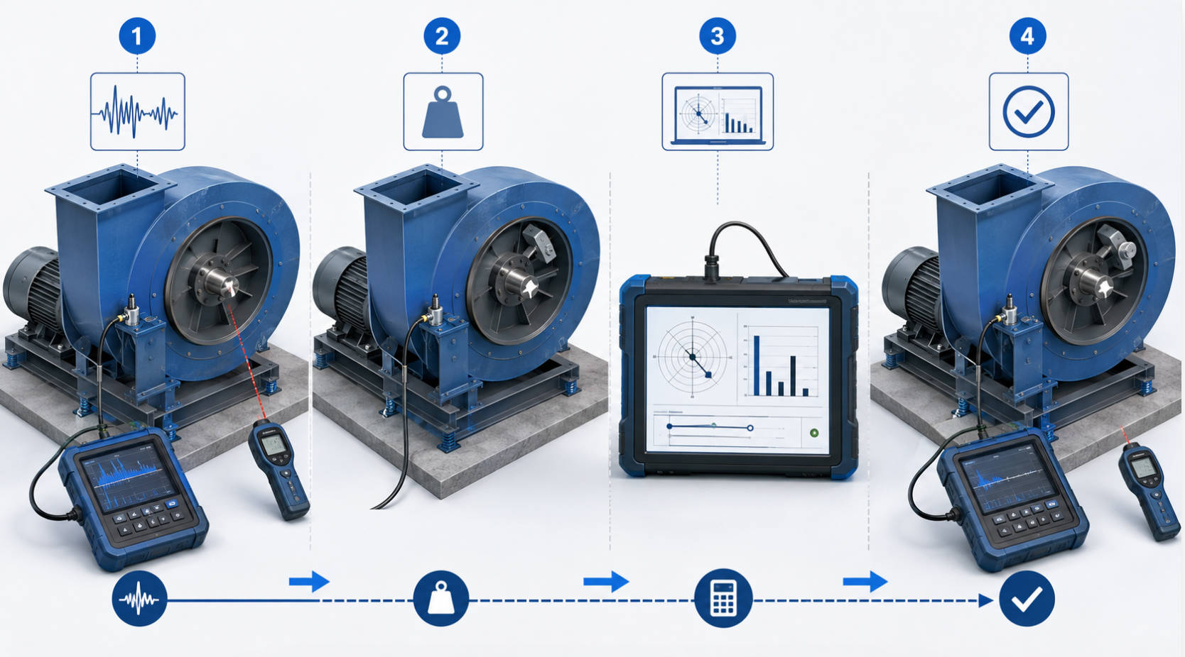
Dynamic balancing should be completed by trained technicians using suitable instruments. The objective is not only to reduce vibration but also to identify whether imbalance is truly the dominant fault.
Install accelerometers near the bearing housings or at appropriate structural measurement points. Add a phase reference, typically reflective tape on the shaft and a laser tachometer.
Run the fan at its normal operating speed and collect:
- Rotational speed in RPM
- Overall vibration value
- 1× running-speed vibration amplitude
- Phase angle
- FFT vibration spectrum
- Operating condition, including damper position or airflow setting
A strong and stable 1× RPM component often indicates imbalance. However, multiple harmonics, unstable phase, or sharp vibration changes at certain speeds may point to looseness, misalignment, rubbing, or resonance.
Before applying a trial weight, check the entire rotating assembly. Tighten loose mounting bolts, inspect bearings, verify belt tension where relevant, and check motor-to-fan alignment.
A technician should also inspect the support frame. A perfectly balanced fan can still show high vibration when installed on a weak bracket or a resonant structure.
Attach a known trial weight at a known radius and angular location. Use a safe and repeatable correction plane, usually the impeller backplate, hub, or manufacturer-provided balancing ring.
Record the exact details:
| Test item | Example record |
|---|---|
| Trial weight | 15 g |
| Correction radius | 120 mm |
| Angular location | 90° from reference mark |
| Plane | Drive side |
| Operating speed | 2,850 RPM |
| Initial vibration | 5.2 mm/s RMS |
| Trial-run vibration | 3.6 mm/s RMS |
The balancing instrument uses the before-and-after response to calculate the influence coefficient. For two-plane balancing, repeat the process at the second correction plane.
The analyzer will recommend a correction mass and angular location. Install the permanent correction using a method suitable for the impeller material, speed, temperature, and operating environment.
For industrial steel impellers, a properly welded balance weight may be appropriate. For compact DC fans and molded blower wheels, the correction may involve controlled material removal, adhesive balancing compound, or a manufacturer-designed balancing feature.
Quality rule: The permanent correction must be as secure and durable as the impeller itself. A loose correction weight can create severe vibration and a safety hazard.
After the correction is installed, repeat the vibration measurement at the same operating condition. Compare the final result with the baseline reading and the application's specified acceptance criteria.
Document:
- Final overall vibration
- Final 1× amplitude and phase
- Final correction mass and location
- Fan speed during verification
- Instrument used and calibration status
- Technician name and date
- Any remaining abnormal vibration frequencies
A balancing attempt will fail if the underlying fault is not imbalance. Use vibration data together with visual inspection and operating history.
| Symptom | Likely cause | Recommended action |
|---|---|---|
| Dominant, steady 1× RPM vibration | Mass imbalance | Perform static or dynamic balancing |
| 1× and 2× RPM vibration | Misalignment | Inspect shaft, coupling, belt drive, and mounting |
| Many harmonics with unstable readings | Mechanical looseness | Check fasteners, bearings, base, and structural joints |
| Sharp vibration peak at one speed | Resonance | Review mounting stiffness and avoid critical speed |
| High-frequency vibration | Bearing defect or electrical issue | Inspect bearings, motor, and drive system |
| Vibration after cleaning | Uneven residual deposits or damaged blade | Reinspect and rebalance if needed |
The most effective maintenance teams do not treat vibration as a single-number problem. They compare the spectrum, phase trend, operating condition, and physical condition of the fan.
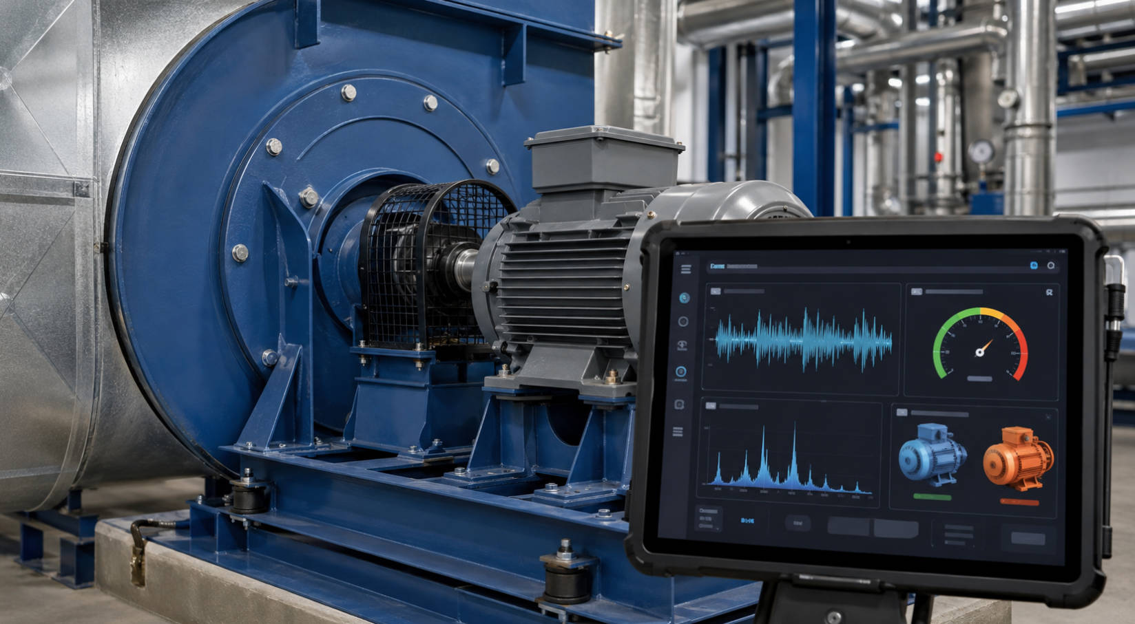
A balanced fan can become unbalanced again because of contamination, corrosion, erosion, accidental impact, blade damage, or component replacement. Preventive maintenance should therefore combine cleaning, inspection, and trend monitoring.
| Frequency | Recommended actions |
|---|---|
| Monthly | Visual inspection, noise check, contamination check, mounting inspection |
| Quarterly | Fastener check, bearing review, vibration trend comparison, belt inspection where applicable |
| After cleaning | Confirm that deposits were removed evenly; perform a vibration check |
| After repair | Inspect geometry and perform balance verification |
| Annually | Detailed vibration analysis and documented performance review |
For dusty, oily, humid, or corrosive environments, increase inspection frequency. In many real applications, the cause of "sudden" imbalance is not sudden at all—it is gradual material build-up that was not noticed early enough.
Fan reliability starts before installation. When specifying a centrifugal fan, OEMs should request more than airflow and static-pressure data.
Ask the supplier about:
- Balance quality and test method
- Factory vibration test capability
- Impeller material and correction method
- Maximum operating speed
- Mounting requirements
- Environmental limits for temperature, dust, humidity, and corrosion
- Availability of vibration data or inspection documentation
- Custom airflow, noise, and reliability validation for the final enclosure
For multi-fan systems, consider airflow interaction as well. Recirculation, inlet turbulence, blocked intakes, and poor mounting stiffness can increase vibration and noise even when each fan is properly balanced.
Capital Technology Co., Limited supports thermal-management projects with CAPITAL DC fans, AC fans, and blower solutions, together with SANYO DENKI fan products. For OEM projects, the most useful approach is to discuss the actual application conditions early: airflow target, pressure requirement, speed range, installation structure, environmental exposure, noise limit, and expected service life.
If your centrifugal fan shows increasing vibration, unusual noise, repeated bearing failure, or unstable cooling performance, do not rely on a visual check alone. Start with a structured inspection, collect baseline vibration data, and determine whether the issue is imbalance, resonance, looseness, or another mechanical fault.
Contact Capital Technology Co., Limited to discuss a DC fan, AC fan, blower, or centrifugal-fan solution matched to your cooling system, reliability target, and operating environment. A properly specified and correctly balanced fan is an investment in quieter operation, stable thermal performance, and lower lifecycle risk.
There is no single interval for every application. Inspect vibration regularly and rebalance after impeller repair, major cleaning, blade damage, material build-up, or a measurable rise in 1× running-speed vibration. High-speed, dusty, or mission-critical installations usually need closer monitoring.
You can perform basic static balancing on a small detached impeller using a low-friction fixture and carefully controlled correction weights. However, dynamic balancing requires vibration and phase measurements, especially for wide, high-speed, or industrial impellers.
The fan may have misalignment, bearing damage, looseness, structural resonance, rubbing, aerodynamic instability, or a weak mounting base. Check the vibration spectrum and mechanical condition before adding further correction mass.
The correct method depends on the impeller design, material, speed, and manufacturer's guidance. Adding a secure weight is common for steel industrial impellers, while controlled material removal may be used for certain compact wheels. Do not alter blades or structural areas without approval.
One-plane balancing corrects a heavy spot in a single axial location. Two-plane balancing corrects both static and couple imbalance across the width of the impeller, making it more suitable for wider and higher-speed rotors.
Balancing primarily reduces vibration and mechanical stress. While it can help avoid losses caused by excessive vibration, rubbing, and poor mechanical condition, overall energy performance also depends on fan selection, system resistance, airflow control, motor efficiency, and installation quality.
1. Longwell Fans, "[How to Balance a Centrifugal Fan: Step-by-Step Guide]." Used as the source article for identifying content-depth, diagnostic, safety, and practical-balancing gaps addressed in this rewrite. [longwellfans]
2. Capital Technology Co., Limited, "[How to Keep Centrifugal Fans Perfectly Balanced: A Practical Guide from an Industry Engineer's Perspective]." Used for the manufacturer and thermal-solution perspective, maintenance framing, and dynamic-balancing workflow. [sanyodenki-cn]
3. Air Movement and Control Association International, "[ANSI/AMCA Standard 204-20: Balance Quality and Vibration Levels for Fans]." Used for the standards-based discussion of fan balance quality and operating vibration. [amca]
4. International Organization for Standardization, "[ISO 21940-12:2016—Mechanical Vibration: Rotor Balancing]." Used for balancing procedures, assessment principles, and balance-quality context for rotating equipment. [iso]
5. Occupational Safety and Health Administration, "[29 CFR 1910.147—The Control of Hazardous Energy (Lockout/Tagout)]." Used for the lockout/tagout safety guidance before maintenance or balancing activity. [osha]
6. Air Movement and Control Association International, "[ANSI/AMCA 204-20 Preview]." Used for additional context on the purpose and scope of fan balance and vibration requirements. [webstore.ansi]


