From idea to market-ready product, our NPI solutions make every stage easier, faster. Discover How We Help
Help Center

Views: 217 Author: Capital Technology Publish Time: 2026-11-07 Origin: Site
Content Menu
● What Is a Plug Fan, and How Does It Work?
>> Axial Inlet, Radial Discharge
>> Why the Plenum Is Part of the Design
● Plug Fan vs. Housed Centrifugal Fan: What Actually Changes?
● AC, DC, and EC Plug Fans: Understanding the Differences
>> EC Plug Fans
>> DC Fans for Equipment Cooling
● Where Plug Fans Deliver Practical Value
>> Air Handling Units and Retrofit Projects
>> Data Centers and Fan Arrays
>> Cleanrooms, Healthcare, and Industrial Recirculation
● How to Select a Plug Fan: A Six-Step Engineering Checklist
>> 1. Define the Required Airflow
>> 2. Establish the Pressure Requirement
>> 3. Select Against the Fan Curve
>> 4. Confirm Installation Geometry
>> 5. Verify Electrical and Environmental Compatibility
>> 6. Compare Sound and Serviceability
● Hidden Performance Risk: Installation System Effects
● How to Compare Plug Fan Energy Costs Fairly
>> Include Part-Load Operation
>> Build a Transparent Cost Comparison
● Fan Wall Redundancy: Verify the Failure Condition
● Choosing a Cooling Partner: Start with the Duty, Not the Catalog
>> 1. Is a Plug Fan the Same as a Plenum Fan?
>> 2. Does a Plug Fan Need an Enclosure?
>> 3. Are All Plug Fans Direct Drive?
>> 4. Are Plug Fans Maintenance-Free?
>> 5. Can an EC Plug Fan Run from AC Mains?
>> 6. What Information Is Needed for an Accurate Quotation?
A plug fan is a centrifugal fan designed to operate without a conventional scroll housing. Often called a casingless fan or plenum fan, it draws air into an impeller and discharges it radially into the surrounding chamber. For air handling units, equipment ventilation, and industrial cooling, this arrangement offers useful installation flexibility—but performance depends on the complete system, not simply the fan.
From an engineering buyer's perspective, the important question is not whether a plug fan is "better" than every alternative. It is whether the selected fan can deliver the required airflow and pressure reliably, efficiently, and within the available space.
This guide explains how plug fans work, where they fit, and what to check before requesting a quotation.
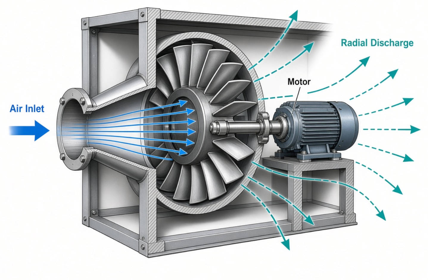
A plug fan typically combines a centrifugal impeller, motor, inlet cone, and mounting structure. Many modern designs use backward-curved blades and direct-drive motors, although industrial plug fans are also available with other drive arrangements.
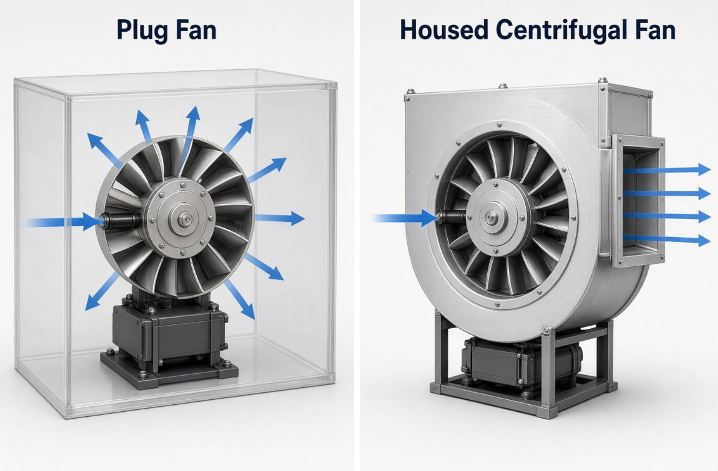
Unlike a housed centrifugal fan, it has no scroll casing to collect air and direct it through a defined outlet.
Air enters approximately parallel to the motor shaft through the impeller inlet. The rotating blades then accelerate the air outward, discharging it around the wheel.
This distinction matters: a plug fan is not an axial fan that moves air straight through its rotor.
The surrounding plenum receives the discharged air and allows some velocity pressure to convert into static pressure. That pressure drives air through downstream filters, coils, ducts, and other components.
Removing the scroll housing does not remove the need for an enclosure.
The plenum's dimensions, wheel clearances, inlet conditions, and outlet locations influence installed performance. A suitable fan can underperform when installed too close to a wall or behind an obstructed inlet.
My recommended selection principle is straightforward: evaluate the fan and its installation space together.
A plug fan belongs to the centrifugal fan family. The meaningful comparison is therefore between an unhoused arrangement and a scroll-housed arrangement—not between two unrelated operating principles.
| Selection factor | Plug fan / plenum fan | Scroll-housed centrifugal fan |
|---|---|---|
| Air discharge | Radially into a surrounding plenum | Through a defined casing outlet |
| Installation | Depends on suitable chamber geometry | Depends on suitable inlet and outlet connections |
| Space requirements | Can simplify compact or modular layouts | Requires room for the scroll and connections |
| Drive options | Direct drive or belt drive, depending on design | Direct drive or belt drive |
| Maintenance | Direct-drive versions eliminate belt servicing | Maintenance depends on the drive arrangement |
| Best-fit applications | AHUs, fan arrays, recirculation chambers | Applications benefiting from a directed discharge |
Neither design automatically wins on efficiency or sound.
Compare actual selections at the same airflow, pressure, air density, and installation conditions. A modern housed fan can also use an efficient motor and variable-speed control.
"Plug fan" describes the mechanical arrangement. AC, DC, and EC describe aspects of the motor or electrical design.
These terms should not be treated as interchangeable.
An AC induction motor can drive a plug fan directly or through a belt arrangement. Suitable motor-and-drive combinations can provide variable-speed operation using a variable frequency drive.
Therefore, AC fans are not necessarily limited to fixed-speed operation.
Check motor compatibility, speed range, protection requirements, and the proposed control method before specifying a drive.
EC means electronically commutated. These fans combine a permanent-magnet motor with electronic control, often integrated into the fan assembly.
Many EC plug fans accept AC mains power. Their electronic commutation does not mean they require an external DC supply.
Depending on the model, control options may include:
- 0–10 V speed commands.
- PWM control.
- Modbus communication.
- Speed feedback and alarm signals.
- Closed-loop pressure or airflow control.
Interfaces vary by product. Confirm the wiring diagram and control functionality rather than assuming every EC fan offers every feature.
DC fans remain relevant for electronics, telecommunications equipment, and other systems with a suitable DC power architecture.
However, a compact DC axial cooling fan is not automatically a replacement for an AHU plug fan. The required airflow direction, pressure capability, dimensions, and electrical supply determine the appropriate solution.
Plug fans can simplify AHU layouts and make modular replacement possible. Direct-drive designs also remove belt tensioning, pulley alignment, and belt-generated debris.
However, a retrofit is not always a drop-in exchange.
Before removing the existing fan, check access openings, mounting loads, electrical capacity, controls, vibration isolation, and available plenum space. The replacement must meet the current system duty—not merely resemble the original fan's nameplate.
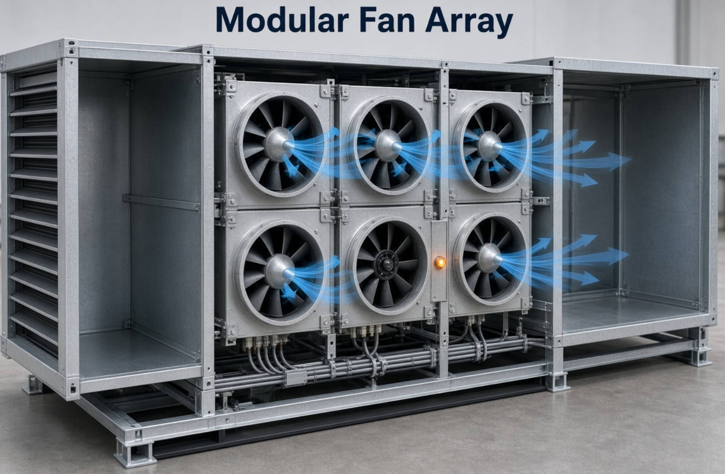
Multiple plug fans can operate in parallel as a fan wall. This arrangement supports modular capacity and can provide redundancy when correctly designed.
Additional fans alone do not guarantee uninterrupted cooling. Controls, reserve capacity, power distribution, and failed-fan isolation all affect the outcome.
Accessible impellers and belt-free drives can support cleaning and inspection. Nevertheless, a casingless design does not automatically establish hygiene compliance.
Materials, drainage, access, cleaning procedures, and the complete air-handling assembly remain important.
For industrial recirculation, also verify temperature limits, corrosion resistance, contamination tolerance, and any hazardous-area requirements. A standard ventilation fan should not be assumed suitable for process exhaust.
Specify airflow in m³/h, L/s, or CFM, and make the units explicit.
Use the actual ventilation or thermal requirement rather than automatically copying an existing selection. Identify minimum, normal, and peak operating conditions where demand varies.
Include resistance from relevant components:
- Filters at their specified operating condition.
- Heating and cooling coils.
- Ductwork and fittings.
- Dampers, grilles, and silencers.
- Other equipment in the airflow path.
Keep the pressure definition consistent. Fan static pressure and fan total pressure are different quantities; the requirement and performance curve must use compatible definitions.
The operating point occurs where the fan curve intersects the system resistance curve.
Request performance data showing airflow, pressure, speed, and electrical input power at the intended duty. Maximum free-air airflow is not a meaningful substitute for performance under resistance.
Also check how the selection behaves as filters load or system demand changes.
Measure the chamber, inlet clearance, wheel clearances, service access, and equipment entry route.
Ask the supplier to review the actual arrangement. There is no single clearance rule that safely replaces model-specific installation guidance.
Confirm:
- Voltage, phase, and frequency.
- Maximum current and protective devices.
- Control interface and feedback signals.
- Ambient and airstream temperature limits.
- Required ingress protection.
- Material compatibility with the environment.
Ask for sound data at the selected operating point, not a general "low-noise" claim.
Review access for inspection, cleaning, motor replacement, and electrical isolation. Direct drive reduces maintenance tasks; it does not eliminate them.
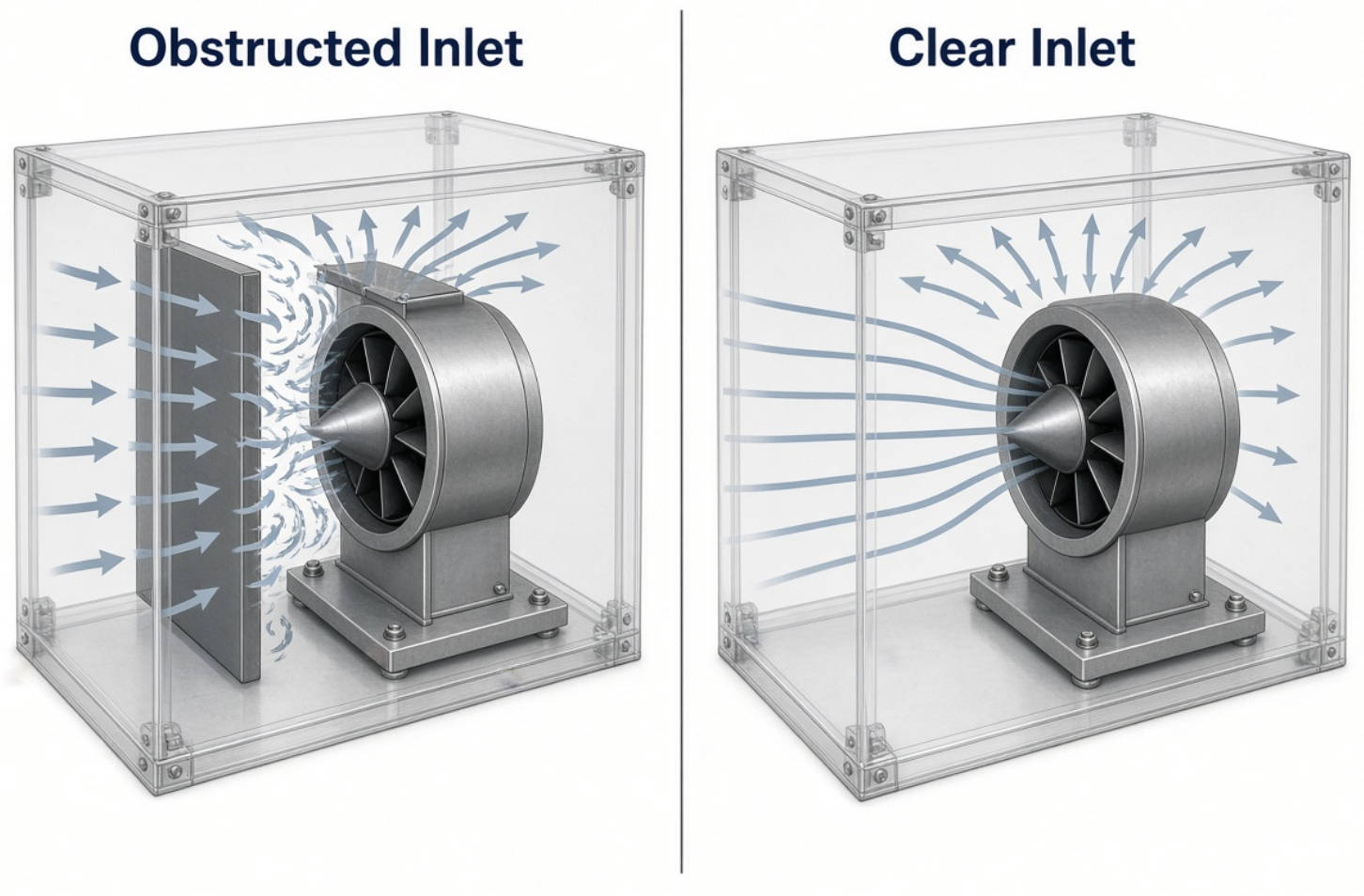
One of the most expensive selection mistakes is assuming laboratory performance will remain unchanged in any cabinet.
System effect describes performance losses caused by installation conditions that differ from the fan's test arrangement.
Typical contributors include an obstructed inlet, abrupt transitions, nearby walls, and unsuitable airflow approaches.
The response should not automatically be "increase the speed." Higher speed can increase power demand and noise while leaving the underlying airflow problem unresolved.
A practical review sequence is:
1. Compare the installed geometry with the supplier's guidance.
2. Identify restrictions and uneven inlet airflow.
3. Improve the arrangement where possible.
4. Recheck the required operating point.
5. Confirm motor capacity and speed limits before making adjustments.
For procurement teams, this is an important distinction: a larger motor cannot guarantee that a poorly integrated fan will become an efficient system.
Motor efficiency alone does not establish the most economical selection. The impeller, motor, electronics, drive arrangement, and installation losses all influence electrical consumption.
Compare electrical input power at the same required airflow and pressure.
Where available, Fan Energy Index provides a duty-point-based comparison of fan-system energy performance. It is more informative than comparing motor power ratings alone.
For variable-demand systems, request performance at representative reduced-load conditions as well as the design point.
Speed reduction can produce substantial power savings under suitable conditions, but actual savings depend on the system curve, control strategy, and component efficiencies.
Avoid treating a theoretical fan-law relationship as a guaranteed electricity-bill reduction.
Use:
Annual energy cost = electrical input power × operating hours × electricity tariff.
For variable operation, calculate each operating period separately and add the results.
Document the assumed hours, power values, and tariff. Then include purchase cost, installation work, maintenance, controls, and expected replacement needs.
This produces a defensible lifecycle comparison rather than an unsupported savings percentage.
An N+1 arrangement should retain the required duty with one fan unavailable. That must be demonstrated through selection data and control design.
Do not simply divide total airflow by the installed fan count.
When one fan stops, the remaining fans operate at a different point. Air may also pass backward through the inactive opening unless the design addresses that possibility.
Request confirmation of:
- Delivered airflow and pressure with one fan unavailable.
- Remaining fans' speed and electrical loading.
- Backflow prevention or isolation strategy.
- Alarm detection and automatic response.
- Shared controller and power-supply failure risks.
For critical cooling, redundancy is a verified system capability—not a label attached to a group of fans.
Capital Technology Co., Limited focuses on DC fans, AC fans, and thermal-management solutions through its CAPITAL brand and SANYO DENKI distribution business.
Our view is that useful fan discussions begin with application requirements rather than a preferred product category.
For an initial technical enquiry, provide:
- Required airflow and pressure.
- Available installation dimensions or drawings.
- Supply voltage and control requirements.
- Temperature, environmental, and sound limits.
- Operating schedule and redundancy expectations.
Ask CAPITAL to review the application and discuss suitable product options. Confirm model availability, performance documentation, and application suitability before finalizing the specification.
The terms often overlap because both describe centrifugal fans operating without a conventional scroll housing. Industrial manufacturers may distinguish particular mounting arrangements, so verify the product drawing and intended installation.
It normally operates within a suitable chamber or equipment enclosure. "Casingless" means the fan lacks its own scroll casing; it does not mean the surrounding installation is unimportant.
No. Direct-drive designs are common, especially in modern EC applications, but belt-driven industrial plug fans also exist. Specify the required arrangement rather than relying on the category name.
No. Direct-drive models remove belt-related servicing, but impellers, bearings, electrical connections, mounting hardware, and protective devices still require attention according to the manufacturer's instructions.
Yes, many models are designed for AC mains and contain integrated motor-control electronics. Check the specific voltage, phase, wiring, and control requirements before connection.
Provide airflow, pressure definition, electrical supply, installation dimensions, environmental conditions, and control requirements. Include normal and peak duty points so the quotation reflects actual operation.
1. Longwell. "What Is a Plug Fan? The Ultimate Guide to Casingless Fan." Original article reviewed for scope, terminology, and content gaps. [longwellfans]
2. Greenheck. "Plug Fans." Technical catalog covering unhoused operation, industrial applications, drive arrangements, and air-density correction. [content.greenheck]
3. Greenheck. "Understanding Fan System Effects." Guidance on installation-related performance losses, airflow obstructions, and the consequences of compensating with increased speed. [greenheck]
4. Greenheck. "Fan Energy Index (FEI): A Practical Metric to Assist the Industry in Selecting the Most Energy-Efficient Fans for an Application." Explanation of duty-point electrical power and wire-to-air comparison. [content.greenheck]
5. Greenheck. "Plenum Fans—Models APD, APF, APM, APH and HPA." Product-selection guidance addressing performance, operating costs, and redundancy selection. [content.greenheck]
6. Greenheck. "Fan Arrays—Models HPA and MOA." Technical catalog discussing array configurations, controls, and operation following fan loss. [content.greenheck]
7. ebm-papst. "EC Plug Fans in AHU Applications: Best Practice Guide." Guidance on mains-powered EC motors, integrated drives, controls, and electrical integration. [ebmpapst]
8. ebm-papst. "EC Centrifugal Fans—RadiCal." Technical catalog covering backward-curved impellers, integrated electronics, supply options, and model-dependent control interfaces. [ebmpapst]
9. Capital Technology Co., Limited. Company background supplied for this article, including the CAPITAL brand and SANYO DENKI distribution relationship. No public verification page was supplied.


