From idea to market-ready product, our NPI solutions make every stage easier, faster. Discover How We Help
Help Center

Views: 242 Author: Capital Technology Publish Time: 2026-10-07 Origin: Site
Content Menu
● Why Airflow, Static Pressure, and RPM Matter in Fan Selection
● What Does Airflow Mean in a Sanyo Denki Fan?
>> Maximum Airflow Is a Free-Air Value
>> Airflow and Thermal Performance
● What Does Static Pressure Mean?
>> Why Static Pressure Is Often Misunderstood
>> Maximum Static Pressure Is Not a Normal Operating Condition
>> When High Static Pressure Is Necessary
● What Does RPM Mean in Fan Specifications?
>> RPM, Airflow, and Static Pressure Relationship
● Airflow vs. Static Pressure: The Core Comparison
>> The P-Q Curve Explains Actual Fan Performance
>> Why the Operating Point Matters More Than the Catalog Maximum
● How to Read a Sanyo Denki Fan Data Sheet
>> Key Specifications to Review
>> Example: Why Two Similar Fans Can Perform Differently
● A Step-by-Step Sanyo Denki Fan Selection Method
>> 1. Define the Heat Load and Temperature Target
>> 3. Estimate or Measure System Resistance
>> 4. Identify the Required Operating Point
>> 6. Compare Noise, Power, and Reliability
>> 7. Validate With a Prototype Test
● Real-World Selection Example: Telecom Power Equipment
● Expert Design Tips for Better Cooling Performance
>> Improve the System Before Increasing Fan Speed
>> Use PWM Control Strategically
>> 1. What is more important: airflow or static pressure?
>> 2. Does a higher RPM always mean a better cooling fan?
>> 3. Why is the actual airflow lower than the fan's rated CFM?
>> 4. How do I choose a high-static-pressure Sanyo Denki fan?
>> 5. What is the difference between maximum airflow and maximum static pressure?
>> 6. Can two fans improve cooling performance?
>> 7. Should I choose a DC fan or AC fan?
● Choose Fans Based on Real Installed Performance
Selecting a Sanyo Denki fan is not simply a matter of choosing the highest CFM or the highest RPM. In real electronic equipment, the correct cooling fan must deliver sufficient airflow at the actual resistance level of the system while meeting requirements for noise, power consumption, reliability, installation space, and controllability.
For telecom cabinets, network switches, base stations, industrial control equipment, power supplies, charging systems, and high-density electronics, engineers often compare airflow, static pressure, and RPM. These three parameters are closely connected, but they do not mean the same thing. Understanding the difference is essential for choosing the right San Ace DC fan, AC fan, or customized thermal solution.
At Capital Technology Co., Limited, we support customers with CAPITAL cooling fans and SANYO DENKI San Ace fan solutions. Based on our experience serving demanding communications and industrial applications, one principle remains consistent: a fan's catalog maximum is not its real installed performance.

A cooling fan operates inside a complete system, not in open air. Air must travel through restrictions such as:
- Fan guards and protective grilles
- Air filters
- Heat sinks
- Dense PCB layouts
- Cable bundles
- Narrow ventilation channels
- Power modules
- Louvers and vents
- Dust accumulation over time
These restrictions create resistance. The fan must generate enough pressure to overcome that resistance and maintain the airflow required to remove heat.
A fan with an impressive free-air airflow rating may perform poorly after installation if the system is highly restrictive. Conversely, a high-static-pressure fan may be unnecessary for an open enclosure with a short, low-resistance airflow path.
For this reason, fan selection should focus on the operating point, not only the maximum airflow or maximum static-pressure figure in a catalog.
| Parameter | What It Means | Common Units | Why It Matters |
|---|---|---|---|
| Airflow | The volume of air moved by a fan over time | CFM, m³/min, m³/h | Determines how much heat can be carried away |
| Static pressure | The fan's ability to push air against system resistance | Pa, mmH₂O, inch H₂O | Determines whether airflow can pass through restrictive components |
| RPM | The rotational speed of the fan impeller | RPM or min⁻¹ | Influences airflow, pressure, noise, and power use |
| Power input | Electrical energy consumed by the fan | W | Affects energy use and power-supply sizing |
| Sound pressure level | Noise generated during operation | dB(A) | Important for workplace, telecom, medical, and commercial equipment |
| Expected life | Estimated bearing and motor operating life under stated conditions | Hours | Supports reliability planning and maintenance design |
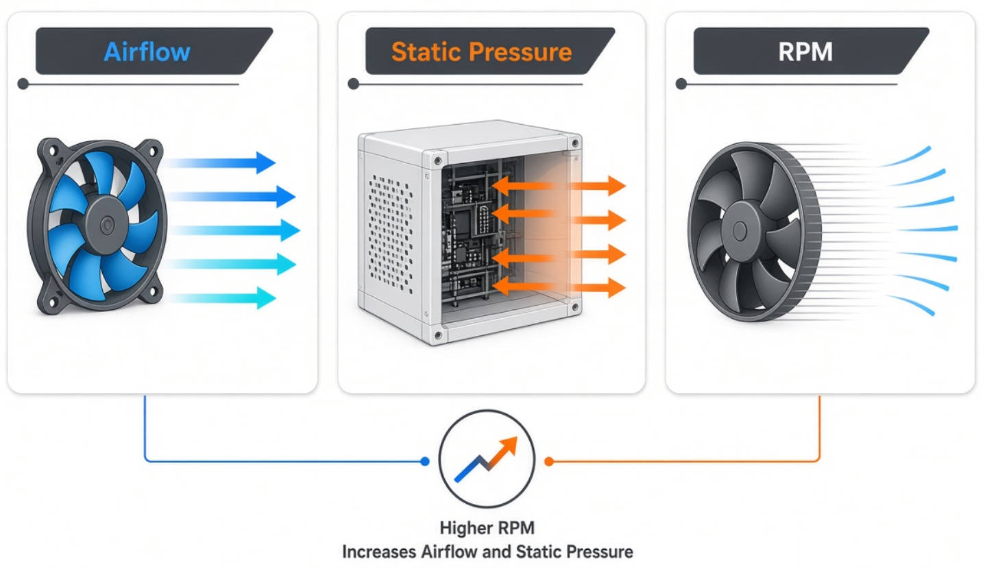
The key lesson is simple: airflow moves heat, static pressure overcomes resistance, and RPM is one of the main controls that affects both.
Airflow is the amount of air a fan can move in a given period. It is commonly shown as CFM, meaning cubic feet per minute, or as cubic meters per minute.
For example, a fan rated at 100 CFM can theoretically move 100 cubic feet of air per minute under a specified test condition. However, this value is usually measured with little or no external restriction.
A fan's maximum airflow is usually measured when static pressure is close to zero. In other words, the air inlet and outlet are not significantly blocked.
This is useful for comparing product families, but it is not the final airflow your equipment will receive after installation.
Consider two applications:
| Application | Airflow Path | Selection Priority |
|---|---|---|
| Open industrial cabinet | Large vents, limited internal obstruction | Higher airflow may be the primary priority |
| 1U server or telecom chassis | Narrow channels, heat sinks, dense boards, fan guards | High static pressure is often more important |
| Power supply | Transformer, inductors, heatsinks, compact enclosure | Balanced airflow and static pressure |
| Outdoor communication equipment | Filters, sealed housing sections, dust exposure | Static pressure margin and speed control |
| Battery energy storage system | Long air channels and multiple thermal zones | Stable airflow distribution and pressure capability |
In practice, an engineer should ask: How much air actually reaches the hot components?
That question is more important than the maximum CFM printed in a data sheet.
Airflow removes heat by carrying warmer air away from components and replacing it with cooler air. More airflow can improve cooling performance, but only when the air follows an effective path across the heat-generating parts.
Poor airflow direction can create:
- Hot spots around processors or power devices
- Recirculation of warm exhaust air
- Uneven temperature distribution
- Dust concentration in sensitive areas
- Higher fan speed with limited cooling improvement
- Excessive noise without meaningful thermal benefit
An effective design does not merely move a large volume of air. It creates a controlled airflow path from intake to exhaust.
Static pressure describes a fan's capability to push air through resistance. It is often measured in Pascals (Pa) or inches of water gauge (inch H₂O).
A fan with higher static pressure can better maintain airflow when installed behind filters, heat sinks, guards, narrow ducts, and other restrictions.
Many buyers see high CFM and assume the fan will deliver strong cooling in every system. This is not always true.
A high-airflow fan can perform well in open space but lose a large share of its airflow when resistance rises. A high-static-pressure fan is designed to maintain stronger performance as the system becomes more restrictive.
SANYO DENKI defines static pressure as the fan's ability to move air against resistance caused by the internal structure of the equipment. This is especially important in compact and high-power-density electronics, where air passages are often narrow.
Maximum static pressure is measured when airflow is zero. This occurs when the fan outlet is fully blocked.
Likewise, maximum airflow occurs when static pressure is zero. Since neither condition represents a typical installed application, they should not be treated as the expected operating condition.
The real operating condition lies somewhere between those two points.
| Catalog Condition | Airflow | Static Pressure | Typical Meaning |
|---|---|---|---|
| Free-air condition | Maximum | Near zero | Open airflow path with minimal resistance |
| Fully blocked condition | Near zero | Maximum | Fan is pushing against a closed or fully restricted path |
| Real equipment condition | Moderate to high | Moderate to high | Actual installed operating point |
High-static-pressure cooling fans are often preferred in systems with:
- Compact heat sinks
- Fine-fin heat exchangers
- High-density circuit boards
- Small vent openings
- Long or narrow airflow channels
- Fan guards with limited open area
- Air filters
- Dense cable routing
- Dust-filtered outdoor enclosures
- 1U and 2U rack-mounted equipment
For example, SANYO DENKI's San Ace high-static-pressure fan designs are developed for demanding electronic cooling environments where fan resistance is high. Some compact models provide exceptionally high pressure capability relative to their frame size, making them suitable for tightly packaged communication and power-electronics systems.
RPM means revolutions per minute. It indicates how fast the fan's impeller rotates.
Higher RPM generally increases airflow and static pressure. However, it can also increase noise, vibration, power consumption, and bearing stress.
RPM should not be treated as a direct indicator of cooling performance by itself. A fan's blade shape, motor design, frame depth, bearing system, and airflow path all affect its final performance.
For similar fan conditions, the general fan relationships are:
Where:
- Q = airflow
- P = static pressure
- W = power
- N = fan speed or RPM
This means:
- Airflow changes approximately in proportion to RPM
- Static pressure changes approximately with the square of RPM
- Power consumption changes approximately with the cube of RPM
A 20% RPM reduction may lower airflow by roughly 20%, but the static pressure capability can fall by roughly 36%. The power reduction can be much larger.
This is why PWM speed control is valuable. It allows equipment designers to reduce noise and energy use during normal operation while retaining higher cooling capacity when internal temperatures increase.
Assume a fan operates at 10,000 RPM.
If the speed increases to 12,000 RPM:
- Airflow may increase by about 20%
- Static pressure may increase by about 44%
- Power demand may increase by about 73%
This is only an engineering approximation. Actual performance must always be verified using the manufacturer's P-Q curve and the system resistance curve.
Airflow and static pressure are not competing specifications. They work together.
The best fan is the one that provides the required airflow at the pressure created by your system.
| Comparison Point | Airflow | Static Pressure |
|---|---|---|
| Primary function | Moves air volume | Pushes air through resistance |
| Best represented by | CFM or m³/min | Pa or inch H₂O |
| Most important in | Open or low-restriction equipment | Dense, filtered, narrow, or obstructed equipment |
| Maximum catalog condition | No external resistance | Fully blocked airflow path |
| Main design question | How much air is needed? | How difficult is it for air to pass through? |
| Common selection mistake | Selecting only by maximum CFM | Ignoring pressure losses from system components |
| Effect of higher RPM | Increases approximately linearly | Increases approximately with the square of speed |
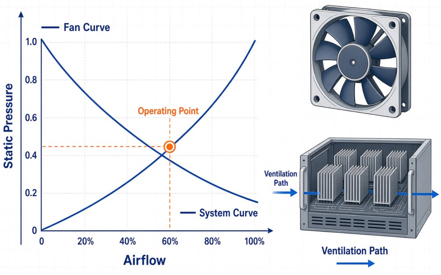
A P-Q curve, also called an airflow-static-pressure curve, shows how a fan performs across different resistance conditions.
The horizontal axis usually represents airflow. The vertical axis represents static pressure.
As resistance increases:
- Static pressure rises
- Actual airflow falls
- The fan reaches a specific operating point
Your equipment also has a resistance curve, often called a system curve. The point where the fan curve and system curve meet is the actual operating point.
This is the value that should guide fan selection.
Suppose Fan A has a higher maximum airflow than Fan B. At first glance, Fan A may appear to be the better choice.
However, if the system has a restrictive filter, dense heat sink, and narrow exhaust vent, Fan A may lose airflow quickly. Fan B may have lower free-air CFM but a stronger pressure curve. In that system, Fan B can provide more useful airflow through the equipment.
The correct fan is not necessarily the fan with the largest CFM number. It is the fan with the best performance at your required operating point.
A professional fan selection process should review more than airflow, static pressure, and RPM. The data sheet provides a complete picture of fan suitability.
1. Rated voltage
Confirm compatibility with the equipment power supply, such as 5 VDC, 12 VDC, 24 VDC, or 48 VDC.
2. Operating voltage range
Check the guaranteed voltage range, especially for systems with voltage fluctuations.
3. Rated current and input power
Ensure the power supply can support startup and full-speed fan operation.
4. Rated speed
Use RPM as a performance reference, not as the only selection criterion.
5. Maximum airflow
Use this to understand free-air capability.
6. Maximum static pressure
Use this to assess performance in restricted systems.
7. P-Q curve
Compare it with the system resistance curve to identify the likely operating point.
8. Sound pressure level
Confirm whether the noise level is suitable for the intended environment.
9. Operating temperature
Verify that the fan can reliably operate at the expected ambient temperature.
10. Expected life
Consider continuous-duty applications, maintenance requirements, and product life-cycle expectations.
11. Sensor and control options
Consider pulse output, lock sensor, alarm output, and PWM speed control for system monitoring.
A 40 mm fan with a shallow frame may have limited pressure capability. A 40 mm × 28 mm high-performance fan can often generate far higher static pressure because of its deeper frame, motor design, blade geometry, and higher speed.
This difference matters in compact network devices and power modules, where every millimeter of airflow path can create additional resistance.
The data sheet must therefore be read as a complete engineering document, not as a list of isolated numbers.
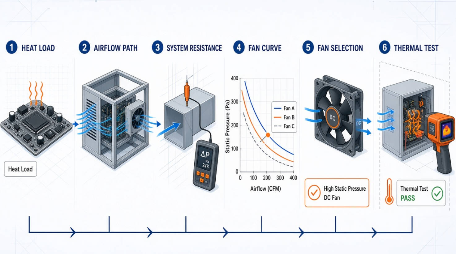
The following process can help engineers, OEM buyers, and thermal-design teams select an appropriate Sanyo Denki cooling fan.
Start with the thermal requirement.
Identify:
- Total power dissipation
- Major heat-generating components
- Maximum allowable component temperature
- Ambient temperature range
- Required temperature rise limit
- Continuous or intermittent duty cycle
Do not select a fan before defining the thermal objective.
Review the enclosure layout and identify restrictions.
Pay attention to:
- Inlet and outlet positions
- Fan guard open area
- Filter condition
- Heat-sink fin direction
- PCB orientation
- Cable routing
- Internal partitions
- Areas where hot air may recirculate
A small design change in vent geometry or cable routing can reduce pressure loss and improve cooling performance without increasing fan speed.
System resistance increases as airflow increases. A simplified relationship is:
Ps = CQ2
Where:
- Ps = static pressure
- Q = airflow
- C = system resistance coefficient
A high value of C indicates a more restrictive system.
Whenever possible, measure the operating airflow and pressure on the actual equipment. This is more reliable than selecting a fan based only on theoretical assumptions.
Determine the airflow needed to maintain safe temperatures, then identify the corresponding system pressure.
This required airflow-pressure combination is the target operating point.
Select candidate fans whose P-Q curves pass close to the required operating point.
Avoid choosing a fan that barely meets the requirement. Include practical design margin for:
- Filter loading
- Dust accumulation
- Manufacturing variation
- High ambient temperature
- Component aging
- Voltage variation
- Installation tolerance
If multiple fans meet the thermal requirement, compare them at the actual operating point.
Choose the solution that offers the best balance of:
- Cooling performance
- Noise level
- Energy use
- Life expectancy
- Cost
- Availability
- Control method
- Mechanical compatibility
The final step is testing.
Measure:
- Component temperatures
- Airflow direction
- Fan speed
- Sound pressure level
- Input current
- Alarm and tachometer performance
- Thermal performance at high ambient temperature
- Performance with a partially loaded filter, if relevant
This validation step prevents design decisions based only on free-air fan values.
Consider a compact telecom power module installed in a rack cabinet. The enclosure includes:
- High-power conversion components
- Dense PCB assemblies
- Aluminum heat sinks
- A finger guard
- Limited air inlet area
- Narrow exhaust openings
- Potential dust exposure in field conditions
A buyer may initially select a fan based on maximum airflow. However, the system contains multiple restrictions, so the actual airflow could be far lower than the free-air CFM rating.
In this situation, the recommended approach is:
1. Measure or estimate the system resistance
2. Identify the required airflow to keep power devices within the target temperature
3. Review the San Ace fan P-Q curves
4. Select a model with adequate pressure capability at the target airflow
5. Consider PWM control to reduce acoustic noise during low-load conditions
6. Test the equipment at maximum ambient temperature and expected filter condition
A high-static-pressure DC fan can be a more effective choice than a higher-CFM general-purpose fan if the system resistance is significant.
This is particularly relevant to telecommunications equipment, industrial control panels, charging systems, servers, and power supplies, where airflow paths are rarely unrestricted.
Fan selection is only part of a successful thermal design. The enclosure and internal layout also determine cooling efficiency.
Before upgrading to a faster fan, review the equipment design.
- Increase inlet and outlet open area where possible
- Use low-resistance fan guards
- Align heat-sink fins with the airflow direction
- Avoid placing cables directly in front of fan inlets
- Prevent exhaust air from returning to the inlet
- Seal unwanted bypass gaps
- Use smooth airflow channels instead of abrupt turns
- Maintain sufficient clearance at fan inlet and outlet
- Design filters for acceptable pressure loss and serviceability
- Consider multiple fan locations for large or thermally divided enclosures
A lower-resistance system may allow a quieter and more energy-efficient fan to achieve the same thermal result.
PWM-enabled fans can adjust speed according to the equipment temperature.
This offers important benefits:
- Lower noise during normal operation
- Lower average power consumption
- Longer bearing life under reduced-speed operation
- Higher cooling capacity available during thermal peaks
- Better temperature stability
- Easier integration with intelligent monitoring systems
For high-value network, telecom, and industrial equipment, fan-speed feedback and failure alarms can further improve maintenance planning and system reliability.
Neither is universally more important. Airflow is critical for heat removal, while static pressure is critical for overcoming resistance. Open enclosures usually prioritize airflow. Dense, filtered, or compact equipment usually needs stronger static-pressure capability.
No. A higher RPM can increase airflow and static pressure, but it can also increase noise, vibration, and power consumption. The best fan is the one that meets the required operating point efficiently.
Rated maximum CFM is generally measured under low-resistance conditions. In installed equipment, guards, filters, heat sinks, vents, cables, and PCB components create resistance, reducing the airflow delivered by the fan.
First, estimate or measure your system resistance. Then compare the system curve with the fan's P-Q curve. Select a fan that delivers the required airflow at the pressure level created by the equipment, with sufficient margin for real operating conditions.
Maximum airflow occurs when the fan faces almost no resistance. Maximum static pressure occurs when airflow is completely blocked. Real applications operate between these two conditions.
Yes. Two identical fans in parallel can increase airflow potential, while two fans in series can increase pressure capability. Actual gains may be lower than theoretical values because of airflow interference, enclosure layout, and fan spacing.
DC fans are widely used in electronic equipment because they support compact designs, speed monitoring, PWM control, low-voltage operation, and intelligent thermal management. AC fans can be suitable for certain industrial systems that use mains power and require simpler fixed-speed operation. The best choice depends on voltage availability, control needs, enclosure size, and reliability requirements.
A successful Sanyo Denki fan selection starts with the complete thermal system, not with the highest airflow number in a catalog. Airflow tells you how much air a fan can move. Static pressure tells you how effectively it can push that air through resistance. RPM influences both, while also affecting noise and power consumption.
For a compact, high-density, or filtered enclosure, focus on the P-Q curve and operating point. For a low-resistance enclosure, airflow may be the leading selection parameter. In either case, prototype validation remains essential.
Capital Technology Co., Limited can support your project with CAPITAL DC fans, AC fans, and SANYO DENKI San Ace cooling-fan solutions. Share your equipment dimensions, voltage, target airflow, installation space, temperature conditions, and system restrictions to receive a more accurate fan-selection recommendation.
1. SANYO DENKI. "Fan Airflow and Static Pressure." Tech Compass—Fan Basics. Available at: [https://techcompass.sanyodenki.com/en/training/cooling/fan_basic/004/index.html]
2. SANYO DENKI. "DC Fan Catalog: How to Read Specifications." San Ace DC Fan Catalog. Available at: [https://www.sanyodenki.com/america/document/DC_Fan.pdf]
3. SANYO DENKI. "Development of the San Ace Airflow Tester: A Measuring Device for System Impedance and Operating Airflow of Equipment." SANYO DENKI Technical Report No. 42. Available at: [https://www.sanyodenki.com/archive/document/corporatedata/technicalreport/2016/TR42E_p18_AirflowTester.pdf]
4. SANYO DENKI. "San Ace 38 9HVA Type DC Fan." Product news, October 9, 2024. Available at: [https://www.sanyodenki.com/america/products/product_news/2024/20241003_sanace_38hva_dc-fan.html]
5. SANYO DENKI. "San Ace 92 9HV Type 92 × 92 × 25 mm High Static Pressure Fan." Product news, November 4, 2020. Available at: [https://www.sanyodenki.com/america/products/product_news/2020/20201104_sanace_92hv25.html]
6. Air Movement and Control Association International. "ANSI/AMCA Standard 99-25: Standards Handbook." Available at: [https://www.amca.org/assets/resources/public/publish/ansi-amca-99-25-standards-handbook-5.1.25.pdf]


