From idea to market-ready product, our NPI solutions make every stage easier, faster. Discover How We Help
Help Center

Views: 211 Author: Capital Technology Publish Time: 2026-10-17 Origin: Site
Content Menu
● High Airflow vs High Static Pressure: Quick Comparison
● What Does High Airflow Mean in a San Ace Fan?
>> Maximum Airflow vs Actual Cooling Airflow
>> Where High-Airflow Performance Is Most Useful
● What Does High Static Pressure Mean in a San Ace Fan?
>> Maximum Static Pressure Does Not Mean Maximum Cooling
>> Where High-Static-Pressure Performance Matters
● How to Read the San Ace Airflow–Static Pressure Curve
>> Why the Operating Point Matters More Than Either Maximum
>> Avoid Drawing a Straight Line Between Endpoints
● Real San Ace Specifications: What the Numbers Actually Show
● Three Practical Insights That Improve Fan Selection
>> 1. Compare Fans at the Same Cooling Requirement
>> 2. Validate Clean and Loaded Filter Conditions
>> 3. Treat Airflow Bypass as a Separate Problem
● A Six-Step Workflow for Choosing the Right San Ace Fan
>> Step 1: Define the Thermal Requirement
>> Step 2: Identify the Resistance Sources
>> Step 3: Obtain the System Impedance Curve
>> Step 4: Overlay Candidate Performance Curves
>> Step 5: Check Integration Details
>> Step 6: Validate the Complete Equipment
● Noise, PWM Control, and Multiple-Fan Arrangements
>> PWM Control Helps Match Cooling to Demand
>> Series and Parallel Fans Solve Different Problems
● Choosing a Cooling Partner, Not Just a Part Number
>> 1. Is a high-static-pressure San Ace fan always better?
>> 2. Can a San Ace fan provide both high airflow and high static pressure?
>> 3. Should I choose a fan by CFM or static pressure?
>> 4. Does a thicker fan always produce more static pressure?
>> 5. Can I replace an AC fan with a San Ace DC fan?
>> 6. Will installing two fans double the airflow?
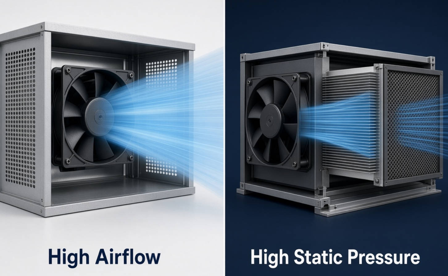
Choosing a San Ace fan with high airflow vs high static pressure starts with understanding your equipment's airflow resistance. A high-airflow fan prioritizes moving a large volume of air through a relatively open path. A high-static-pressure fan prioritizes maintaining useful airflow through restrictions, such as dense heatsinks, filters, and tightly packed electronics.
However, these are not mutually exclusive capabilities. Every fan has both airflow and pressure characteristics. The right choice depends on its operating point inside your equipment—not simply the highest CFM or pressure number in a catalog.
At Capital Technology Co., Limited, our approach to cooling selection starts with the complete system. Whether considering our CAPITAL products or SANYO DENKI's San Ace range, we recommend matching fan performance to the enclosure, thermal load, and operating requirements.
| Comparison factor | High-airflow priority | High-static-pressure priority |
|---|---|---|
| Main objective | Move substantial air through an open path | Maintain airflow against resistance |
| Typical environment | Spacious enclosures and large ventilation openings | Dense electronics, filters, and restrictive heatsinks |
| Important specification | Airflow available at the required system pressure | Pressure available at the required airflow |
| Common selection mistake | Treating maximum CFM as installed airflow | Treating maximum pressure as cooling capacity |
| Main evaluation tool | Fan performance curve and system resistance | Fan performance curve and system resistance |
| Practical decision | Favor airflow when resistance is low | Favor pressure capability when resistance is high |
Neither approach is universally better. An oversized pressure-focused fan may add unnecessary power consumption and noise, while an airflow-focused model may underperform behind a restrictive filter.
Airflow describes the volume of air a fan moves per unit of time. Common units include cubic feet per minute, or CFM, and cubic meters per minute.
Moving air through equipment carries heat away. However, useful cooling depends on how much air reaches heat-generating components, not merely how much leaves the fan.
Maximum airflow is measured at approximately zero static pressure, with minimal resistance at the fan's inlet and outlet.
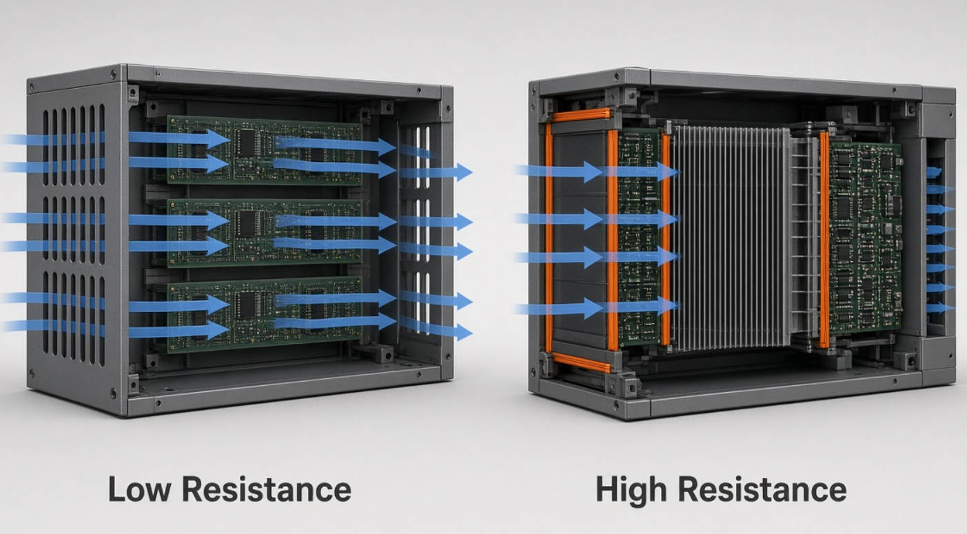
Once installed, the fan encounters:
- Ventilation grilles and finger guards.
- Filters and protective screens.
- Circuit boards and internal wiring.
- Heatsink fins and duct transitions.
- Restricted inlet or discharge clearances.
These features change the operating conditions. A fan rated for 118 CFM does not automatically deliver 118 CFM through an assembled cabinet.
For purchasing teams, this distinction is critical: catalog airflow is a comparison parameter, not a guaranteed system result.
Airflow-oriented selection is a logical starting point for equipment with broad openings, short airflow paths, and relatively low internal resistance.
Examples include spacious control cabinets and electronics enclosures with generous ventilation areas.
Even here, air distribution matters. Air that bypasses a hot component contributes less to cooling that component than air directed through its heatsink.
Static pressure describes the pressure a fan develops to overcome airflow resistance. It is commonly expressed in pascals, or Pa, and inches of water.
A pressure-capable fan can maintain useful airflow through more restrictive passages. This becomes especially important when packaging constraints limit vent area or component spacing.
Maximum static pressure occurs at zero airflow, when the airflow path is blocked.
Consequently, maximum static pressure and maximum airflow represent opposite endpoints of the fan's performance curve. They do not occur simultaneously.
A high pressure rating indicates capability against resistance. It does not, by itself, show how much cooling air will pass through your equipment.
Pressure-focused selection is particularly relevant for:
- High-density servers and network switches.
- Telecommunications equipment with crowded circuit boards.
- Power supplies with narrow internal passages.
- Filtered industrial enclosures.
- Closely spaced heatsink fins.
The common factor is resistance—not simply heat generation. A high-power device with an open cooling path and a lower-power device behind a restrictive filter may require very different fan characteristics.
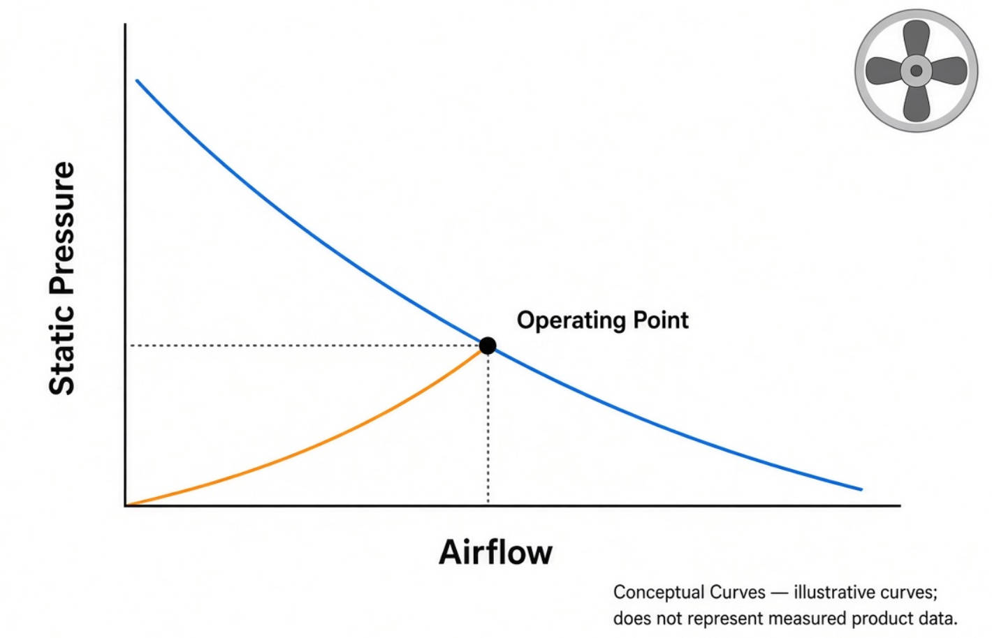
The airflow–static pressure curve, also called the P–Q curve, connects airflow on the horizontal axis with pressure on the vertical axis.
Your equipment has its own resistance characteristic, known as the system impedance curve.
The intersection of these two curves determines the installed operating point.
Consider two hypothetical candidates:
- Fan A has higher maximum airflow.
- Fan B has lower maximum airflow but maintains greater pressure across the required airflow range.
In an open enclosure, Fan A may move more air. In a restrictive enclosure, Fan B may deliver more useful airflow.
The result depends on where each curve intersects the system curve.
This is why our preferred comparison question is: "How much airflow can this fan deliver at our required pressure?"
It is more useful than asking which model has the largest headline specification.
Two maximum values are insufficient to reconstruct a fan's actual performance curve.
Curve shape varies by model, speed, and aerodynamic design. Selection should use the manufacturer's published curve rather than an assumed straight line between maximum airflow and maximum pressure.
Published San Ace specifications illustrate why airflow and pressure must be evaluated together.
| Specification | San Ace 92 9HV | San Ace 38 9HVA |
|---|---|---|
| Model | 9HV0912P4G001 | 9HVA0312P3K001 |
| Dimensions | 92 × 92 × 25 mm | 38 × 38 × 28 mm |
| Rated voltage | 12 V | 12 V |
| Maximum airflow | 118 CFM | 32.2 CFM |
| Maximum static pressure | 280 Pa | 2,100 Pa |
| Rated input | 14.76 W | 25.2 W |
| Published sound pressure level | 56 dB(A) | 69 dB(A) |
These are differently sized products, not interchangeable alternatives or a controlled comparison of fan designs.
Both belong to high-static-pressure product families. Nevertheless, the larger model has greater maximum airflow, while the smaller model has substantially greater maximum pressure.
The practical lesson is that physical size, pressure capability, airflow, power, and acoustics must be considered together. Neither model is "better" without knowing the installation requirements.
These figures are published specifications from their respective product announcements, not measurements from a CAPITAL customer installation.
Comparing two fans only at full speed can produce a misleading commercial conclusion.
Instead, compare candidates at the same required installed airflow. Then evaluate:
- Input power at the selected operating condition.
- Equipment-level noise.
- Available control range.
- Remaining cooling margin.
- Mechanical and electrical compatibility.
A powerful fan operated below full speed may be appropriate, but lower noise or power consumption should be verified rather than assumed.
A filtered enclosure does not maintain identical resistance throughout its service life. Dust accumulation can increase restriction and shift the operating point.
For filtered applications, define at least two test conditions:
1. A clean filter representing initial installation.
2. A specified loaded-filter condition representing maintenance limits.
Check airflow and component temperatures under both conditions. Avoid adding an arbitrary percentage margin without connecting it to actual operating requirements.
A stronger fan cannot guarantee that air follows the desired route.
Gaps around heatsinks or poorly sealed ducts may allow air to bypass the components needing cooling.
Before increasing fan power, inspect the airflow path. Improving ducting, sealing bypass gaps, or clearing an obstructed inlet may be more effective than changing the fan alone.
Document heat dissipation, maximum inlet temperature, component temperature limits, and expected operating conditions.
A first-pass heat balance can estimate airflow requirements. However, component hotspots and uneven airflow still require physical validation.
List filters, grilles, heatsinks, ducts, wiring bundles, and narrow passages.
Evaluate the assembled enclosure, not an empty housing that excludes production components.
Measure system resistance where practical. SANYO DENKI's San Ace Airflow Tester is designed to measure system impedance and operating airflow.
Early estimates can support preliminary selection, but measured data provides a stronger basis for final decisions.
Find each candidate's operating point against the same system curve.
Confirm that the resulting airflow meets the thermal requirement at the intended speed and supply voltage.
Review dimensions, mounting arrangement, connector, wiring, voltage range, speed feedback, and control requirements.
For PWM-controlled models, verify signal compatibility and the model's specified speed-control behavior.
Test component temperatures, installed airflow, noise, vibration, and electrical input.
Repeat relevant tests at demanding ambient temperatures and resistance conditions. Retain the results as part of the product qualification record.

Pulse-width modulation, or PWM, allows compatible fans to adjust speed through an external control signal.
This enables cooling to respond to changing thermal conditions instead of running continuously at maximum speed.
However, the control strategy must preserve adequate airflow during high load. Check startup behavior, minimum-speed operation, and failure responses for the specific model.
For identical fans under ideal conditions:
- Series operation increases pressure capability at a given airflow.
- Parallel operation increases airflow capability at a given pressure.
Real installations do not necessarily achieve the theoretical gains. Fan interaction, spacing, leakage, and enclosure resistance affect performance.
Do not assume that adding a second fan doubles installed cooling. Validate the combined arrangement, especially when redundancy is required.
Capital Technology Co., Limited is a source manufacturer of DC fans, AC fans, and cooling solutions, with its independent CAPITAL brand and a SANYO DENKI agency business.
For engineering and procurement teams, the selection discussion should begin with application data rather than a request for "the highest CFM fan."
Share your enclosure dimensions, thermal load, operating voltage, temperature limits, filter arrangement, and current fan information with Capital Technology Co., Limited. Request a San Ace shortlist supported by performance curves, integration requirements, and a defined validation plan.
No. It is valuable when resistance limits airflow. In an open enclosure, a different model may meet the cooling requirement with more suitable power, acoustic, or dimensional characteristics.
Yes. These capabilities are not mutually exclusive. However, maximum airflow and maximum static pressure occur at different test conditions, so selection still requires the complete performance curve.
Use both. First determine the required airflow and system resistance. Then select a fan whose performance curve provides sufficient airflow at that resistance.
No. Thickness alone is not a reliable selection rule. Impeller geometry, motor capability, speed, and frame design influence performance. Compare specific model curves instead.
Not as a direct electrical substitution. Check the available DC supply, voltage, current capacity, dimensions, wiring, controls, and installed performance before considering a replacement.
Not necessarily. Parallel fans can increase airflow capability, but actual airflow depends on the combined fan characteristic and system resistance. Series arrangements primarily increase pressure capability.
1. SANYO DENKI, "Fan Airflow and Static Pressure," *Fan Basics, Lesson 4*. Technical basis for airflow, pressure, operating points, speed relationships, and multiple-fan arrangements. [techcompass.sanyodenki]
2. SANYO DENKI America, "SANYO DENKI Launches 92 × 92 × 25 mm High Static Pressure Fan," November 4, 2020. Specifications for model 9HV0912P4G001 and PWM functionality. [sanyodenki]
3. SANYO DENKI America, "SANYO DENKI Develops 38 × 38 × 28 mm DC Fan with the Highest Static Pressure and Airflow in the Industry," October 9, 2024. Specifications for model 9HVA0312P3K001. [sanyodenki]
4. SANYO DENKI, "Airflow Tester," San Ace product information. Measurement capabilities for system impedance, operating airflow, and P–Q performance. [products.sanyodenki]
5. SANYO DENKI, "Fans with PWM Control," *San Ace Cooling Systems Technical Materials*. PWM operation and temperature-responsive control examples. [products.sanyodenki]
6. SANYO DENKI, "Technical Center Support Case 2: Selecting the Best Fan in a System." Application workflow covering impedance, airflow requirements, operating points, and acoustic evaluation. [sanyodenki]
7. Capital Technology Co., Limited, company background supplied for this article. Basis for the CAPITAL brand, manufacturing scope, and SANYO DENKI agency description; no independently verified public document supplied.


