From idea to market-ready product, our NPI solutions make every stage easier, faster. Discover How We Help
Help Center

Views: 221 Author: Capital Technology Publish Time: 2026-10-13 Origin: Site
Content Menu
● San Ace Fan CFM vs Static Pressure: The Core Differences
● What Does CFM Mean for San Ace Cooling Fans?
>> Maximum CFM vs Actual Installed Airflow
>> When CFM Deserves More Attention
● What Does Static Pressure Mean for San Ace Fans?
>> Why Maximum Static Pressure Is Not a Cooling Result
● The P–Q Curve Explains Which Specification Matters More
>> The Operating Point Is the Real Selection Target
● Published San Ace Specifications: What the Numbers Reveal
● A Practical Cooling Calculation: Translate Heat into Required Airflow
>> Example: A 300-Watt Electronics Enclosure
● Three Application Scenarios That Change the Answer
>> Open Industrial Control Enclosures
>> Dense Telecommunications Equipment
>> Filtered Cabinets and Heat Exchangers
● Expert Selection Workflow: Compare Fans at the Same Duty Point
>> Include Degraded Conditions in Validation
● PWM Control, Noise, and Power: Avoid Oversizing by Habit
>> Compare Acoustic Specifications Carefully
● Common Mistakes in San Ace Fan Selection
● Choose the Right Cooling Solution with Capital Technology
>> 1. Is CFM or Static Pressure More Important for a San Ace Fan?
>> 2. Can a Higher-CFM Fan Deliver Less Air After Installation?
>> 3. Does Higher Static Pressure Always Improve Cooling?
>> 4. Can I Select a San Ace Fan Without a P–Q Curve?
>> 5. How Do Dirty Filters Affect Fan Performance?
>> 6. Do DC, AC, and ACDC Fans Use the Same Selection Principle?
When comparing San Ace fan CFM vs static pressure, the answer depends on the equipment being cooled. CFM describes airflow volume. Static pressure describes the fan's ability to overcome airflow resistance. For an open enclosure, airflow capacity often deserves greater attention. For a dense cabinet with filters, heatsinks, and narrow passages, pressure capability becomes essential.
However, neither maximum specification tells the complete story. The most important selection criterion is operating airflow: the air the fan actually delivers against your equipment's resistance.
At Capital Technology Co., Limited, our approach to cooling selection connects the fan specification with the complete application. As a DC fan and AC fan manufacturer with our own CAPITAL brand and a chief agency role for SANYO DENKI, we frame this comparison around a practical question: which fan can move enough air through your actual equipment?
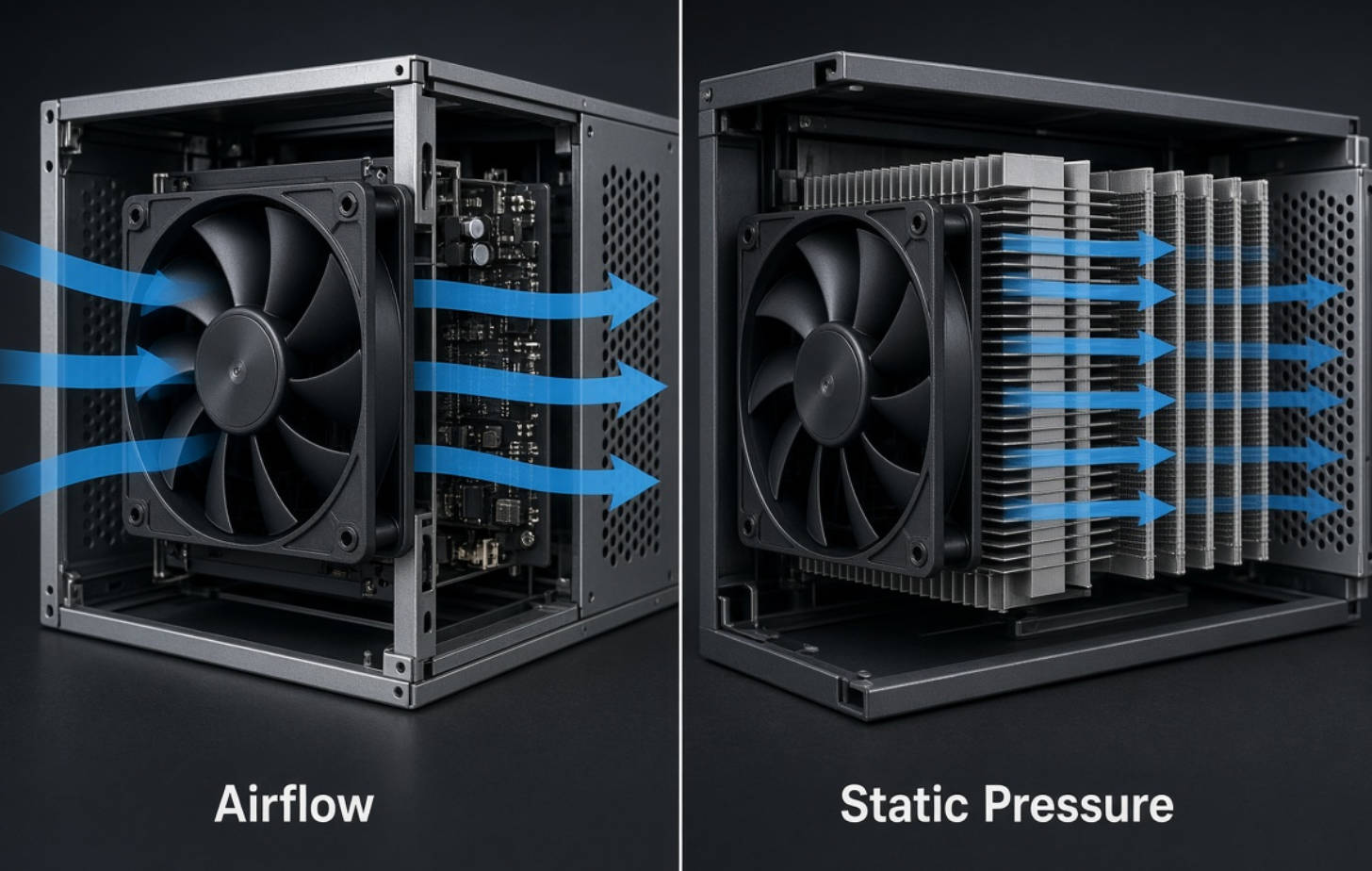
CFM and static pressure describe different aspects of the same fan performance curve. They are not competing measures of quality.
| Comparison | CFM | Static Pressure |
|---|---|---|
| Meaning | Air volume moved per minute | Pressure available to overcome resistance |
| Common units | CFM or m³/min | Pa or inches of water |
| Maximum rating condition | Approximately zero static pressure | Zero airflow |
| Main selection relevance | Potential airflow capacity | Capability against restrictive airflow paths |
| Typical application concern | Removing heat from accessible spaces | Moving air through filters, heatsinks, or dense assemblies |
| Main limitation | Maximum CFM is not installed airflow | Maximum pressure does not indicate useful cooling airflow |
The relationship matters more than either endpoint. A suitable San Ace cooling fan must provide the required airflow at the pressure your system demands.
CFM stands for cubic feet per minute. It measures volumetric airflow, not cooling capacity directly.
Moving more air can improve heat removal, but only when that air passes through the intended cooling path. Air that escapes around a heatsink or recirculates inside a cabinet contributes less useful cooling.
Maximum airflow is measured near zero static pressure. This represents a low-resistance condition, not a typical enclosed installation.
Once a fan encounters a filter, protective grille, circuit board, or heatsink, resistance increases. The delivered airflow generally decreases.
For example, a fan rated at 100 CFM does not automatically supply 100 CFM through a telecommunications cabinet. Its installed airflow depends on the complete pressure–airflow curve and the cabinet's resistance.
That distinction is especially important when buyers compare products using only a catalog summary.
Airflow capacity is especially relevant when:
- Intake and exhaust openings are generous.
- Internal components leave clear airflow passages.
- Filters and heat exchangers create little resistance.
- The main objective is exchanging heated enclosure air.
Even in these applications, confirm the operating point. An enclosure that looks open can still contain restrictive grilles or poorly positioned components.
Static pressure is the pressure difference a fan can develop to move air against resistance.
Manufacturers commonly express it in pascals or inches of water. Approximately 249 Pa equals one inch of water.
Pressure capability becomes important when air must travel through a difficult path. Typical restrictions include:
- Closely spaced heatsink fins.
- Dust filters and protective screens.
- Dense electronics assemblies.
- Narrow ducts or long passages.
- Heat exchangers and compact ventilation openings.
Maximum static pressure occurs at zero airflow. A fan at this endpoint is producing pressure, but it is not delivering useful through-flow for normal forced-air cooling.
Therefore, a model with a higher maximum static pressure does not necessarily deliver more air at every relevant operating condition.
The useful question is not "Which fan has the highest pressure?"
It is "Which fan supplies our required airflow at our required pressure?"
A P–Q curve plots pressure against airflow. Airflow usually appears on the horizontal axis, with static pressure on the vertical axis.
Your equipment also has a resistance curve, often called its system impedance curve. For many fixed turbulent airflow paths, resistance approximately follows:
ΔP=KQ2
Here, ΔP is pressure loss, Q is airflow, and K represents the system's resistance characteristics.
This approximation is useful, but it is not a universal description of every filter or airflow regime.
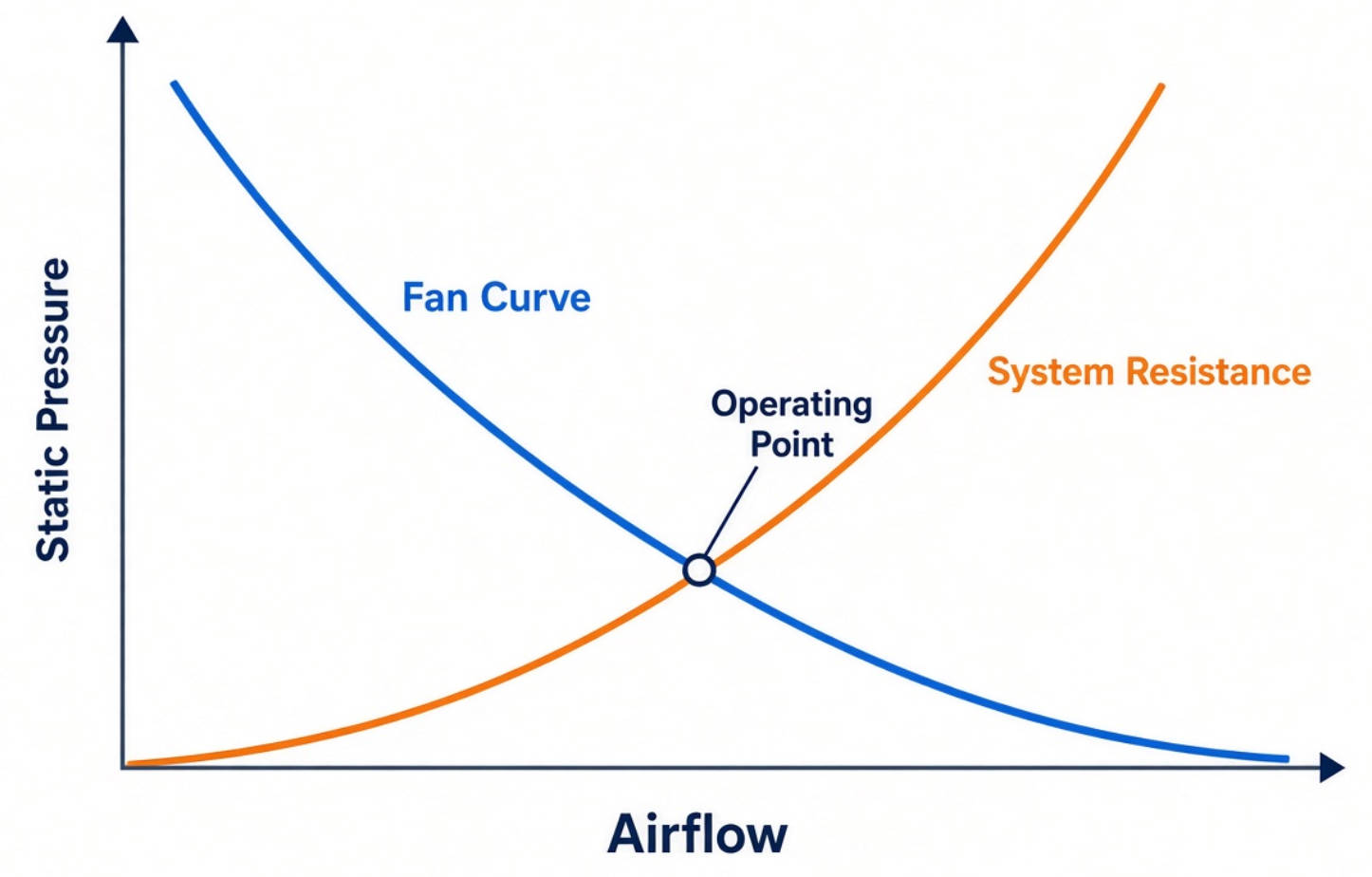
The intersection of the fan curve and system resistance curve establishes the operating point.
At that point, the fan's available pressure matches the pressure required to move the corresponding airflow through the equipment.
Consider two hypothetical fans:
- Fan A has higher maximum CFM but limited pressure capability.
- Fan B has lower maximum CFM but stronger pressure capability.
Fan A may deliver more air in an open enclosure. Fan B may deliver more air through a restrictive heatsink.
Without their curves and the system resistance, the maximum ratings alone cannot identify the better choice.
Actual product specifications demonstrate why airflow and pressure must remain separate.
| San Ace Model | Product Type | Maximum Airflow | Maximum Static Pressure |
|---|---|---|---|
| 9AD0901P4G001 | 92 × 92 × 25 mm ACDC fan | 47.3 CFM | 76 Pa |
| 9HVA0612P1J001 | 60 × 60 × 38 mm high-static-pressure DC fan | 84.3 CFM | 2,000 Pa |
These are published endpoint specifications, not simultaneous operating conditions.
The models also differ in size, supply type, speed, power consumption, and sound pressure level. This is therefore not a like-for-like ranking.
The comparison illustrates a narrower point: frame size alone does not establish pressure capability, and a compact high-speed fan can have very different characteristics from an ACDC enclosure fan.
For procurement, always request the exact part number and its full performance curve. A series name is not enough to verify suitability.
Before comparing fans, estimate how much airflow the application needs.
A simplified sensible-heat balance is:
V˙=P/ρcpΔT
Where:
- V˙ is volumetric airflow in m³/s.
- P is heat transferred to the air in watts.
- ρ is air density.
- cp is air's specific heat capacity.
- ΔT is the permitted bulk air temperature rise.
For near-sea-level conditions using approximately 1.2 kg/m³ air density and 1,005 J/(kg·K) specific heat:
Required CFM≈1.76P/ΔT
Suppose an enclosure transfers 300 W to its ventilation air, with a permitted inlet-to-outlet air temperature rise of 10°C.
The estimated requirement is approximately 53 CFM.
This is required operating airflow, not the fan's free-air rating.
Next, determine the system pressure loss at 53 CFM. Then identify a fan whose curve supports that airflow at the corresponding pressure.
This calculation is a preliminary estimate. It does not predict semiconductor junction temperature or account fully for hotspots, bypass flow, altitude, or heat removed through other paths.
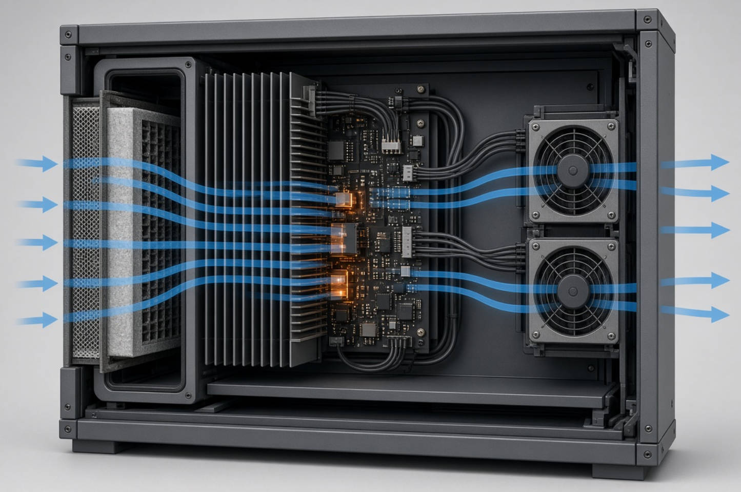
For an enclosure with broad openings and relatively clear internal passages, airflow capacity may be the primary initial filter.
Nevertheless, placement matters. An intake and exhaust positioned too close together can create a shortcut that leaves critical components undercooled.
Evaluate the cooling path, not simply the total volume exchanged.
Telecommunications assemblies can combine circuit boards, shields, cable bundles, and compact heatsinks.
Here, pressure capability often becomes the differentiating factor. A high free-air CFM rating may offer little advantage if the fan curve falls sharply within the required operating range.
Select around airflow through the actual board channels and heatsinks, then validate component temperatures.
Filters and heat exchangers increase resistance. Filter loading can raise it further during service.
Evaluate both clean-filter and specified end-of-service conditions. The fan should meet the thermal requirement before the planned maintenance threshold is reached.
Do not apply an arbitrary percentage margin without understanding the resistance change.
A defensible comparison uses the same required airflow and pressure for every candidate.
1. Establish the heat load, maximum ambient temperature, and component temperature limits.
2. Estimate the minimum required operating airflow.
3. Define the complete airflow path, including filters, grilles, and internal obstructions.
4. Measure system resistance or develop a preliminary model.
5. Compare candidate P–Q curves at the required duty point.
6. Check voltage, input power, control functions, acoustic data, and environmental ratings.
7. Test the shortlisted fan in the final mechanical configuration.
An airflow measurement device, such as the San Ace Airflow Tester, can help establish system impedance and operating airflow.
If resistance is initially unknown, catalog-based allowances can support shortlisting. They should not replace installation testing.

Repeat thermal checks under relevant worst-case conditions:
- Maximum specified ambient temperature.
- Minimum permitted supply voltage.
- Representative filter loading.
- Intended installation orientation.
- Expected altitude or air-density conditions.
- Fan-failure conditions where redundancy is required.
This turns a favorable laboratory result into a more useful assessment of operating reliability.
Selecting the highest-pressure fan available can create unnecessary noise and electrical demand.
PWM-capable San Ace models allow speed adjustment where supported by the specific product. This can help align airflow with changing thermal loads.
For geometrically unchanged fans under comparable conditions, airflow approximately follows rotational speed, while pressure capability approximately follows speed squared.
A speed reduction can therefore reduce pressure capability faster than airflow capability. Confirm reduced-speed performance against the system curve.
Published sound pressure levels are meaningful only alongside their measurement conditions.
Installation can introduce turbulence, vibration, or tonal noise that catalog figures do not fully describe.
For a fair comparison, check:
- Measurement distance and test arrangement.
- Fan speed and control setting.
- Whether the figure represents free-air operation.
- Noise in the completed enclosure.
The preferred fan is the one that meets thermal requirements with acceptable installed noise and power—not necessarily the quietest catalog entry.
Several purchasing shortcuts can undermine otherwise sound cooling designs:
- Treating maximum CFM as guaranteed cabinet airflow.
- Assuming maximum airflow and maximum pressure occur together.
- Comparing different models without checking their curves.
- Increasing fan speed instead of correcting blocked passages.
- Ignoring airflow bypass around the heatsink.
- Selecting solely by frame size or connector compatibility.
- Assuming two fans automatically double airflow or pressure.
Multiple-fan arrangements require evaluation of the combined performance curve, mounting geometry, and system resistance.
A replacement fan should also be checked for control compatibility, current demand, startup behavior, and monitoring functions.
At Capital Technology Co., Limited, we combine CAPITAL DC and AC fan manufacturing with access to SANYO DENKI San Ace products. Our company background includes supplying ZTE, HUAWEI, and HYTERA.
For a useful technical inquiry, send your heat load, enclosure dimensions, available fan space, supply voltage, ambient range, and noise target.
Include the required airflow and pressure when available. If they are unknown, provide the enclosure layout, filter information, and existing fan part number.
Contact Capital Technology to discuss a San Ace or CAPITAL cooling solution matched to your operating conditions—not merely a higher catalog rating.
CFM is often the stronger initial consideration in low-resistance applications. Pressure capability becomes essential in restrictive systems. Final selection should use operating airflow at the required system pressure.
Yes. A higher free-air rating does not guarantee higher airflow against resistance. A lower-rated fan with a more suitable pressure–airflow curve can outperform it in a restrictive enclosure.
No. Higher maximum pressure is useful only when the fan delivers sufficient airflow through the intended cooling path. Component temperatures must still be verified.
You can create a preliminary shortlist, but maximum ratings alone do not establish installed performance. Obtain the curve for the exact model before final selection.
Filter loading generally increases airflow resistance. The operating point can shift toward lower airflow, potentially increasing equipment temperatures. Evaluate the specified service condition and maintenance interval.
Yes. Each must deliver adequate airflow against the application's resistance. Supply requirements, available controls, speed characteristics, and model-specific performance still differ.
1. SANYO DENKI, "Fan Air Volume and Static Pressure," Basic Knowledge of Fans. Supports airflow and pressure definitions, maximum-rating conditions, P–Q curves, and approximate speed relationships. [techcompass.sanyodenki]
2. SANYO DENKI, "Equipment Ventilation Resistance," Basic Knowledge of Fans. Explains system impedance, fan-curve intersections, and operating airflow. [techcompass.sanyodenki]
3. SANYO DENKI, "Guideline in Selecting a Fan," San Ace Technical Material. Provides heat-based airflow estimation, preliminary selection guidance, and the requirement for actual installation testing. The 300-watt example above is an illustrative calculation, not a measured customer result. [products.sanyodenki]
4. SANYO DENKI, "92 × 92 × 25 mm San Ace 92AD 9AD Type ACDC Fan," product announcement. Source for model 9AD0901P4G001 and its published maximum airflow and static pressure. [sanyodenki]
5. SANYO DENKI, "60 × 38 mm 9HVA Type High Static Pressure Fan," product announcement, April 1, 2022. Source for model 9HVA0612P1J001 and its published performance specifications. [sanyodenki]
6. SANYO DENKI, "San Ace Airflow Tester," product information. Describes measurement of system impedance, operating airflow, and pressure–airflow performance. [products.sanyodenki]
7. SANYO DENKI, "Development of the San Ace Airflow Tester—A Measuring Device," Technical Report No. 42, 2016. Supports resistance-curve evaluation and fan selection around the required operating point, with consideration of noise and power. [sanyodenki]


