From idea to market-ready product, our NPI solutions make every stage easier, faster. Discover How We Help
Help Center

Views: 218 Author: Capital Technology Publish Time: 2026-10-21 Origin: Site
Content Menu
● San Ace Counter Rotating Fan vs DC Fan: Key Differences
● How a San Ace Counter Rotating Fan Works
>> Opposing Rotors Improve Pressure Performance
>> Why Two Ordinary Fans Are Not Equivalent
● How a Conventional DC Fan Fits Electronic Cooling
● Compare Installed Airflow, Not Maximum CFM
>> Maximum Airflow and Maximum Pressure Are Different Endpoints
>> The Operating Point Determines Useful Cooling
● Published Product Comparison: Two 80 mm Fan Designs
● Power, Noise, and Mechanical Integration
>> Compare Energy at the Required Cooling Duty
>> Evaluate Noise Inside the Equipment
>> Check Depth, Wiring, and Service Access
● A Six-Step Selection Workflow for High-Density Equipment
>> 1. Define the Thermal Acceptance Criteria
>> 2. Identify the Restrictive Airflow Path
>> 3. Establish System Resistance
>> 4. Shortlist Both Fan Architectures
>> 5. Test Normal and Adverse Conditions
>> 6. Approve the Complete Configuration
● Application Scenarios: When Each Design Makes Sense
>> Dense Communications Equipment
>> Filtered Electronic Enclosure
● Reliability, Sourcing, and Capital Technology's Role
>> 1. Is a San Ace Counter Rotating Fan a DC Fan?
>> 2. Is a Counter Rotating Fan Always Better for Servers?
>> 3. Can I Replace a DC Fan with a Counter Rotating Fan?
>> 4. Does Higher Maximum Static Pressure Guarantee Better Cooling?
>> 5. Can PWM Reduce Counter Rotating Fan Noise?
>> 6. How Should I Compare Fan Service Life?
Choosing a San Ace counter rotating fan vs DC fan for high-density electronic equipment starts with one clarification: a San Ace counter rotating fan is itself a DC-powered fan. The useful comparison is between a dual-rotor, counter-rotating design and a conventional single-rotor DC axial fan.
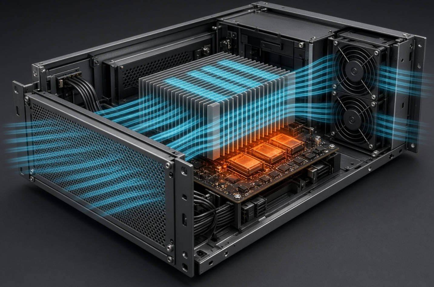
For equipment designers, the deciding factor is usually system resistance—how difficult it is to move air through the enclosure. Dense circuit boards, restrictive filters, and closely spaced heatsink fins can make free-air airflow ratings misleading.
At Capital Technology Co., Limited, our selection approach is application-first: establish the airflow the equipment needs, determine the pressure required to deliver it, and then compare suitable models. This article explains where each fan architecture fits, what published specifications actually mean, and how to make a defensible selection.
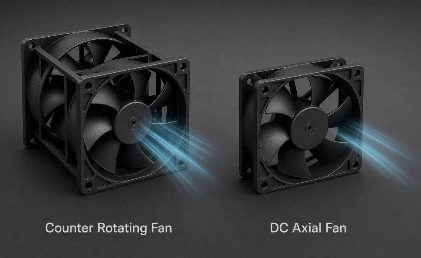
For this comparison, "DC fan" means a conventional single-rotor DC axial fan. Both designs can support electronic cooling, but their aerodynamic structures serve different operating requirements.
| Comparison factor | San Ace counter rotating fan | Conventional DC axial fan |
|---|---|---|
| Rotor arrangement | Two rotors turning in opposite directions | One rotor |
| Primary advantage | Strong pressure capability in restrictive airflow paths | Broad selection of sizes, depths, and performance levels |
| Typical applications | Dense servers, communications equipment, restrictive heatsinks | Control cabinets, power supplies, and less restrictive enclosures |
| Installation depth | Often greater because of the two-stage arrangement | Shallower models are widely available |
| Power and noise | Can be substantial at maximum output; model-dependent | Often lower for modest cooling duties; model-dependent |
| Speed control | PWM available on compatible models | PWM available on compatible models |
| Selection priority | Required airflow against substantial resistance | Required airflow with acceptable pressure, noise, and cost |
Neither architecture is universally superior. A high-pressure fan can be unnecessary in an open enclosure, while a quiet single-rotor fan may underperform behind a restrictive heatsink.
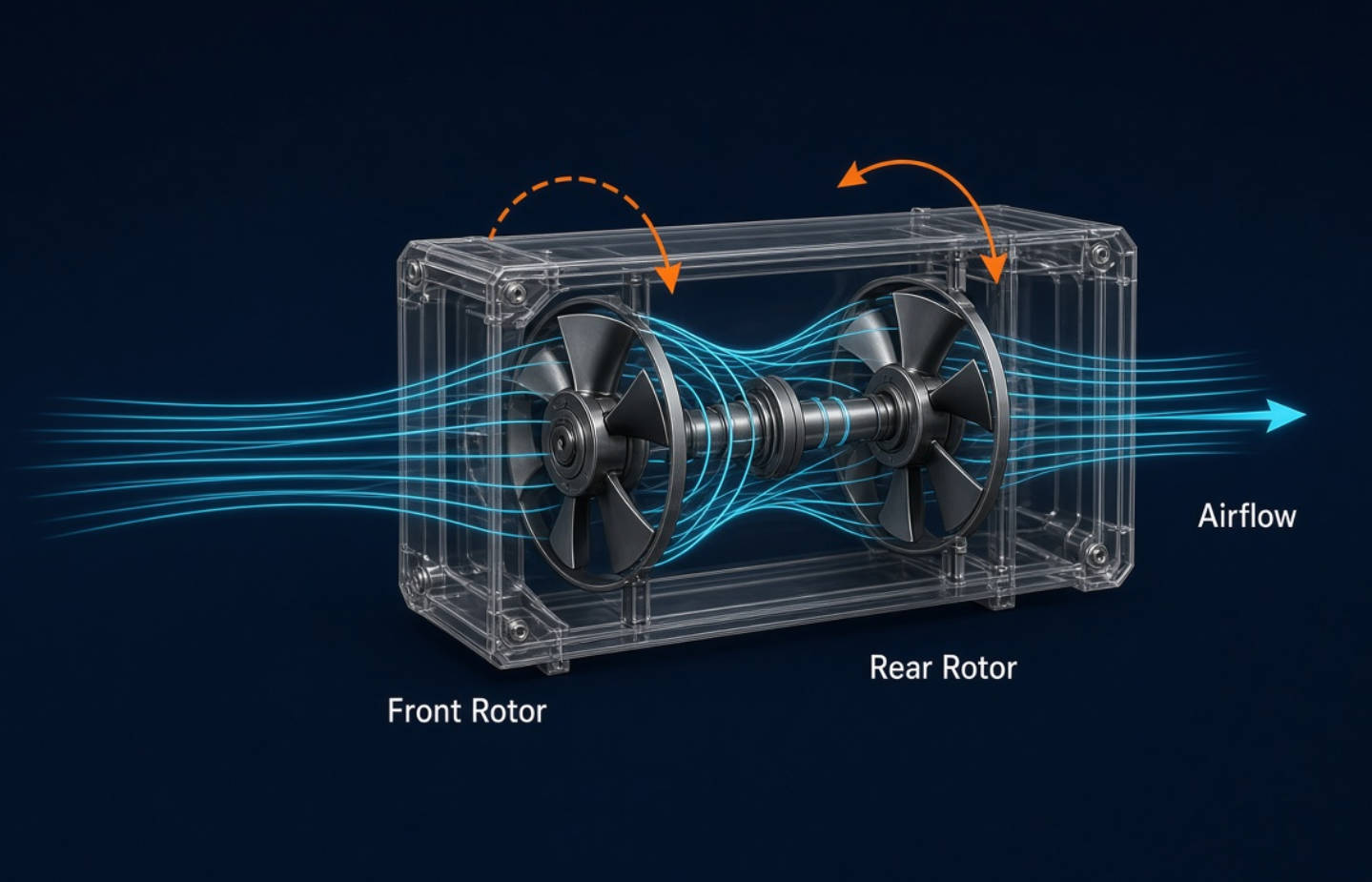
A counter rotating fan places two fan stages along the same airflow axis. The front and rear impellers rotate in opposite directions.
The first stage produces airflow with a swirling component. The second stage counteracts that swirl and helps produce a straighter discharge. SANYO DENKI explains that this arrangement provides substantially higher static pressure than axial fans offering comparable maximum airflow.
This matters when the fan must push air through obstacles rather than simply move air through an unrestricted opening.
Installing two conventional fans in series does not automatically reproduce a purpose-designed counter rotating fan.
Rotor direction, blade geometry, spacing, motor characteristics, and aerodynamic interaction all affect performance. A matched counter-rotating assembly is engineered as a combined system.
For procurement, the practical rule is straightforward: evaluate the assembly's published pressure–airflow curve, not an assumed doubling of individual fan specifications.
A conventional DC axial fan uses one rotor to move air primarily along its axis.
Its appeal is flexibility. Designers can choose from numerous frame sizes, thicknesses, voltage ratings, speed ranges, and control options. This makes single-rotor fans practical for applications where packaging depth, acoustics, or electrical consumption matters more than extreme pressure capability.
For example, a control enclosure with generous ventilation openings may achieve its thermal target without a two-stage fan.
However, "single rotor" does not mean "low performance." High-performance DC axial fans can deliver meaningful static pressure. The correct comparison remains model-specific.
Maximum airflow describes performance near the unrestricted end of a fan's operating curve. Maximum static pressure describes the opposite endpoint, where airflow approaches zero.
These values do not occur simultaneously.
A specification showing high CFM and high maximum pressure does not mean the fan delivers that CFM at that pressure. This distinction is especially important when comparing a counter rotating fan for high-density electronics against a conventional DC cooling fan.
Actual airflow depends on where two curves intersect:
- The fan's pressure–airflow curve.
- The enclosure's airflow-resistance curve.
That intersection is the operating point.
A fan with impressive free-air performance may deliver insufficient airflow after installation. Conversely, a pressure-capable model may maintain useful airflow through restrictive components even when its headline CFM appears unremarkable.
My selection priority would therefore be the operating point first, followed by temperature, noise, power, and commercial requirements.
SANYO DENKI's published specifications illustrate the difference between a pressure-focused counter-rotating design and a single-rotor DC fan.
| Published specification | San Ace 80 counter rotating fan | San Ace 80 DC fan |
|---|---|---|
| Model | 9CRHA0812P8J001 | 9RA0812P1K001 |
| Dimensions | 80 × 80 × 80 mm | 80 × 80 × 38 mm |
| Rated voltage | 12 V | 12 V |
| Maximum airflow | 199 CFM | 104.5 CFM |
| Maximum static pressure | 2,700 Pa | 307 Pa |
| Rated input | 144 W | 18.24 W |
| Published sound pressure level | 85 dB(A) | 53 dB(A) |
| PWM control | Available | Available |
These manufacturer-published examples are not equivalent-duty replacements. They share a frame width but differ substantially in depth, speed, electrical input, and intended performance envelope.
The comparison demonstrates why high pressure carries design consequences. The counter-rotating model provides much greater maximum pressure, but its rated input and published noise are also substantially higher.
It does not prove that every counter rotating fan consumes more energy than every single-rotor fan. Nor does it establish relative efficiency at the same installed operating point. Those conclusions require matched-duty testing.
Rated input is useful for electrical planning, but it does not tell the complete efficiency story.
Compare candidate fans while they deliver the required installed airflow and maintain acceptable component temperatures. A powerful fan operating below maximum speed may behave differently from a smaller fan running continuously at full output.
For PWM-compatible models, speed control can reduce unnecessary operation. Confirm the specified control interface, usable speed range, and behavior when the control signal is absent.
Published sound pressure levels provide a starting point, not a guaranteed enclosure-level result.
Grilles, mounting surfaces, airflow obstructions, and operating speed can affect the finished product's acoustic behavior. Test the assembled equipment, particularly for office, laboratory, or other noise-sensitive installations.
Do not select a high-pressure model solely for thermal headroom without checking whether its acoustic profile suits the installation.
An 80 mm frame does not establish interchangeability.
Confirm:
- Fan depth and mounting-hole arrangement.
- Connector pinout and cable routing.
- Rated voltage and operating range.
- Electrical supply capacity.
- PWM and speed-feedback compatibility.
- Clearance around the inlet and outlet.
- Removal access for maintenance.
A thermally suitable fan can still be an unsuitable mechanical or electrical replacement.
Document maximum inlet temperature, component temperature limits, expected heat load, and operating modes.
Include startup, sustained peak load, and any required degraded-operation condition. A fan specification is not a substitute for a system-level thermal requirement.
Review heatsinks, filters, perforated panels, cable bundles, and board spacing.
Also inspect bypass paths. Air that avoids the hottest components may improve total enclosure airflow without solving the actual thermal problem.
Measure resistance where practical. SANYO DENKI's selection guidance describes using system impedance together with required airflow to establish a suitable operating point.
If early-stage estimates are necessary, treat them as provisional and validate them on representative hardware.
Compare pressure–airflow curves within the available mechanical envelope.
A conventional DC fan remains a valid candidate until the evidence shows that it cannot meet the duty. A counter-rotating design becomes attractive when pressure requirements exceed what suitable single-rotor options can provide.
Validate component temperatures and fan behavior under:
- Maximum intended workload.
- Highest specified inlet temperature.
- Representative filter loading.
- Realistic cable and board configurations.
- Required fan-failure scenarios.
These tests are a proposed validation checklist, not a claim that any particular model already meets your requirements.

Freeze the exact model, connector, control settings, mounting arrangement, and acceptance criteria.
Small integration changes can affect the operating point. Production approval should apply to the tested configuration rather than only to the fan family name.
The following scenarios illustrate selection logic; they are not customer case studies or measured Capital Technology project results.
A communications chassis may combine narrow air channels, closely packed boards, and restrictive heatsinks.
If testing shows inadequate airflow because of pressure loss, a San Ace counter rotating fan deserves evaluation. Increasing free-air CFM alone may not resolve the restriction.
A cabinet with relatively open airflow paths may benefit more from a conventional DC axial fan.
Here, shallow installation depth, moderate noise, and electrical consumption may outweigh the need for extreme pressure capability.
Filter resistance can change during service.
Evaluate the cooling system under a defined loaded-filter condition rather than assuming clean-filter performance will persist. Depending on the required duty, either a pressure-capable single-rotor fan or a counter-rotating model may be appropriate.
Expected life is model- and temperature-dependent. It should not be inferred from rotor count, brand name, or a general product category.
Likewise, two rotors do not automatically establish fault-tolerant cooling. Validate airflow and temperatures under any required failure condition, and confirm available monitoring signals.
Capital Technology Co., Limited supplies DC fans, AC fans, and thermal-management solutions through its CAPITAL brand and SANYO DENKI offering. According to company-provided information, Capital Technology serves as a principal SANYO DENKI agent and has supplied ZTE, HUAWEI, and HYTERA.
Those company credentials provide procurement context; they do not establish performance for a particular equipment design.
For a technically useful recommendation, send Capital Technology your enclosure dimensions, voltage, heat load, temperature limits, acoustic target, and available airflow-resistance data. Request a model-specific shortlist, dimensional drawings, control details, and a validation plan before committing to production.
Yes. The counter-rotating products discussed here are DC-powered fans. The comparison concerns dual-rotor versus conventional single-rotor architecture, not DC versus AC power.
No. It is particularly relevant when ventilation resistance is high. A suitable single-rotor fan may satisfy less restrictive server designs with different power, acoustic, or packaging priorities.
Possibly, but matching frame width is insufficient. Verify depth, voltage, current requirements, connector wiring, control compatibility, mounting, and installed thermal performance.
No. Cooling depends on delivered airflow through the relevant components. Use the operating point and measured component temperatures rather than maximum pressure alone.
On compatible models, reducing speed can lower noise and power consumption. The allowable reduction depends on thermal demand and the model's specified control behavior.
Compare model-specific expected-life ratings under their stated temperature conditions. Also review environmental suitability, monitoring provisions, maintenance access, and the consequences of fan failure.
1. SANYO DENKI. "Features of Counter Rotating Fan." Manufacturer explanation of opposing rotor directions, swirl reduction, and pressure characteristics. [techcompass.sanyodenki]
2. SANYO DENKI. "Equipment Ventilation Resistance." Explanation of system impedance, operating points, and installed airflow. [techcompass.sanyodenki]
3. SANYO DENKI. "80 × 80 × 80 mm Counter Rotating Fan," 9CRHA type, May 2025. Source for model 9CRHA0812P8J001 dimensions and published performance specifications. [sanyodenki]
4. SANYO DENKI. "80 × 80 × 38 mm DC Fan," 9RA type, August 2022. Source for model 9RA0812P1K001 specifications and PWM availability. [sanyodenki]
5. SANYO DENKI. "Technical Center Support Case 2: Selecting the Best Fan." Manufacturer workflow for measuring system impedance and selecting an operating point. [sanyodenki]
6. SANYO DENKI. "Counter Rotating Fan" product information and lineup. Sources for PWM capabilities and model-dependent expected-life specifications. [products.sanyodenki]


