From idea to market-ready product, our NPI solutions make every stage easier, faster. Discover How We Help
Help Center

Views: 231 Author: Capital Technology Publish Time: 2026-10-26 Origin: Site
Content Menu
● San Ace Counter Rotating Fans vs. Conventional Axial Fans
● Why Static Pressure Matters More Than Headline Airflow
>> Read the P–Q Curve, Not Just Maximum CFM
>> Account for the Complete Airflow Path
● Published San Ace Server Fan Specifications Compared
● Electrical Integration, PWM Control, and Noise
>> Check More Than Nominal Voltage
>> Validate the Control Strategy
● Reliability: Two Rotors Do Not Automatically Mean Redundancy
● A Practical Server Fan Validation Workflow
● Working With Capital Technology on Fan Selection
>> 1. Is a San Ace counter rotating fan always better for servers?
>> 2. Are two ordinary fans in series equivalent to a counter rotating fan?
>> 3. Should I prioritize airflow or static pressure?
>> 4. Can PWM control reduce server fan noise?
>> 5. Does a dual-rotor fan provide automatic redundancy?
>> 6. What information should I provide when requesting a quotation?
Selecting a San Ace counter rotating fan for servers starts with a practical question: can it deliver enough airflow through your actual chassis? Dense heatsinks, memory banks, drive cages, and restrictive grilles make free-air specifications insufficient. Engineers must compare pressure capability, electrical demand, control behavior, and reliability—not simply choose the highest CFM rating.
This guide compares San Ace counter rotating fans with conventional single-stage axial fans and explains how to evaluate individual models. From a thermal-design perspective, the deciding factor is the operating point: the airflow and pressure a fan delivers inside the equipment.
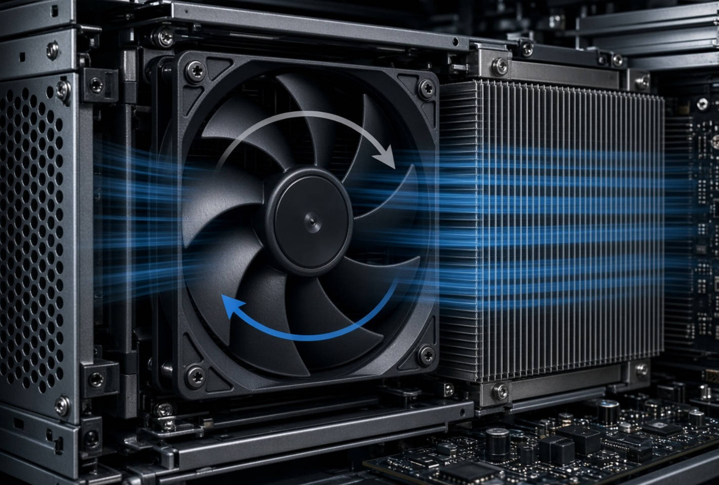
A counter rotating fan combines two coordinated impeller stages rotating in opposite directions. The rear stage reduces the swirling airflow produced by the front stage, helping generate a straighter discharge flow.
This is not equivalent to mounting two identical axial fans in series. Blade geometry and the relationship between stages determine the resulting performance.
| Selection factor | San Ace counter rotating fan | Conventional single-stage axial fan |
|---|---|---|
| Architecture | Two coordinated, opposing stages | One impeller stage |
| Main application advantage | Pressure capability for restrictive airflow paths | Simpler architecture where pressure requirements permit |
| Packaging consideration | Additional depth for two stages | Often easier to accommodate in shallow spaces |
| Electrical assessment | Check complete assembly demand | Check individual fan and array demand |
| Selection priority | Performance against chassis resistance | Sufficient installed airflow with acceptable power and noise |
Neither architecture is universally better. A counter rotating design becomes attractive when a conventional fan cannot meet the required airflow through a restrictive server enclosure.

Maximum airflow is measured at zero static pressure. Maximum static pressure occurs at zero airflow. These values describe different endpoints; they are not delivered simultaneously.
Actual performance occurs where the fan's pressure–airflow curve intersects the chassis resistance curve.
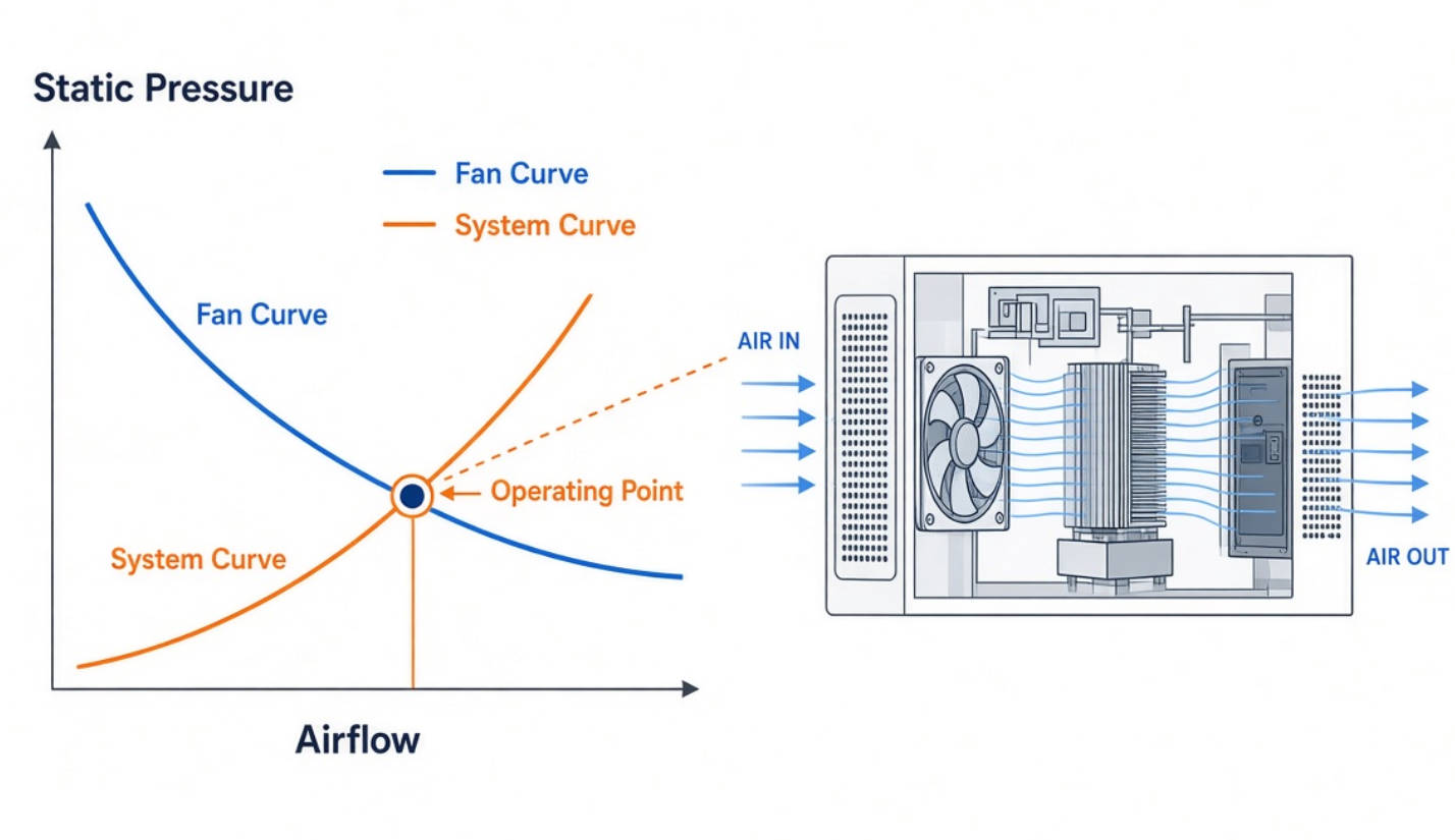
For engineers comparing server cooling fans, this changes the purchasing question:
- Avoid: "Which fan has the highest maximum airflow?"
- Ask: "Which fan delivers our required airflow at the measured chassis pressure drop?"
Also examine whether the operating point falls near an unstable region of the curve. An unsuitable operating region can undermine noise and cooling performance.
Evaluate heatsinks, grilles, cables, connectors, and internal partitions together. A high-pressure fan cannot automatically correct an airflow bypass that lets air avoid the hottest components.
My recommended approach is to assess airflow distribution alongside total airflow. A satisfactory chassis-average temperature can conceal a poorly cooled component.
The following manufacturer-published examples illustrate different package sizes and performance levels. They are not interchangeable drop-in alternatives.
| Model | Dimensions | Rated voltage | Maximum airflow | Maximum static pressure | Rated input | Published SPL |
|---|---|---|---|---|---|---|
| 9CRJ0412P5J001 | 40 × 40 × 56 mm | 12 V | 37.4 CFM | 2,400 Pa | 37.2 W | 72 dB(A) |
| 9CRH0612P6G001 | 60 × 60 × 56 mm | 12 V | 90.8 CFM | 3,350 Pa | 67.2 W | 78 dB(A) |
| 9CRHA0812P8J001 | 80 × 80 × 80 mm | 12 V | 199 CFM | 2,700 Pa | 144 W | 85 dB(A) |
The 40 mm model is specifically positioned for applications including 1U servers. The 60 mm and 80 mm examples illustrate why frame size alone cannot predict pressure capability.
These figures also reveal an important trade-off: substantial pressure performance can accompany substantial electrical and acoustic demands. Compare candidate fans at the required operating point, not merely at their published maximum specifications.
Before approving a high-static-pressure server fan, review:
- Operating voltage range and supply tolerance.
- Rated current and startup requirements.
- Connector, cable, and board-header ratings.
- PWM input requirements and minimum-speed behavior.
- Tachometer outputs and fault-detection arrangements.
Do not assume that two 12 V fans are electrically interchangeable.
For example, the published 144 W input of the 80 mm model corresponds to 12 A at its 12 V rating. That demand deserves explicit review within the server's power-distribution design.
PWM-compatible San Ace models allow external speed control. This enables the system to reduce speed when full cooling performance is unnecessary.
However, a usable control strategy requires more than a PWM signal. Test temperature response, speed transitions, sensor failures, and recovery after thermal excursions.
Published fan sound-pressure levels should not be treated as finished-server noise predictions. Validate acoustics with the actual enclosure, mounting arrangement, grille, and intended fan population.
A counter rotating assembly contains two aerodynamic stages, but that does not establish system-level fault tolerance.
Engineers should verify:
1. How each stage's status is monitored.
2. What airflow remains if one stage stops.
3. Whether the controller can distinguish relevant faults.
4. Whether neighboring modules maintain safe temperatures.
5. Whether replacement requires a server shutdown.
Expected life also requires careful interpretation. Manufacturer life ratings depend on stated conditions, including temperature and voltage. An L10 rating describes the time at which 90% of a population is expected to remain operational under the specified conditions; it is not a guarantee for every unit.
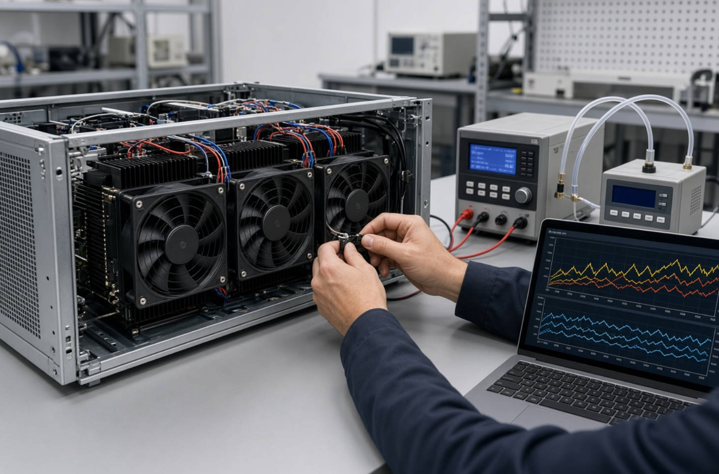
This workflow is a proposed engineering procedure, not a reported customer test.
1. Define acceptance limits. Record component temperature limits, inlet conditions, workload, acoustic targets, and power constraints.
2. Characterize resistance. Measure or establish the enclosure's pressure–airflow relationship.
3. Shortlist by installed performance. Overlay candidate fan curves and identify operating points.
4. Test a representative assembly. Include production-intent heatsinks, cables, grilles, and fan carriers.
5. Sweep operating conditions. Evaluate multiple PWM settings, supply conditions, and relevant inlet temperatures.
6. Introduce credible faults. Test a stopped fan stage or failed module where the architecture allows.
7. Document release criteria. Retain temperature, airflow, noise, power, and fault-response results.
This creates a defensible comparison between counter rotating and conventional axial cooling solutions.
Capital Technology Co., Limited provides DC fan, AC fan, and thermal-management solutions under its CAPITAL brand and through its SANYO DENKI offering.
The company background supplied for this article identifies Capital Technology as SANYO DENKI's chief agent and a supplier to ZTE, HUAWEI, and HYTERA. These are company-provided statements, not independently verified customer endorsements or evidence of a specific server installation.
For a focused selection discussion, send Capital Technology your chassis dimensions, supply voltage, target airflow and pressure, thermal limits, PWM requirements, and connector specification. Request candidate part numbers, current manufacturer documentation, and samples for validation before production approval.
No. Its pressure capability is useful in restrictive designs, but a conventional axial fan may meet the requirement with simpler packaging. Compare installed performance.
No. San Ace counter rotating fans use coordinated opposing stages. Two identical conventional fans do not reproduce the same aerodynamic design.
Evaluate them together on the P–Q curve. The useful result is airflow at the pressure required by your chassis.
It can reduce fan speed when thermal conditions permit. Confirm the resulting temperatures and acoustics in the assembled server.
No. Remaining cooling performance, fault monitoring, and system response must be established through documentation and testing.
Include quantity, dimensions, voltage, operating-point requirements, control interface, connector details, environmental conditions, and qualification expectations.
1. [SANYO DENKI, "Features of Counter Rotating Fan," September 16, 2020]. Source for opposing-stage operation and differences from conventional fans connected in series. [techcompass.sanyodenki]
2. [SANYO DENKI, "Fan Air Volume and Static Pressure," March 12, 2018]. Source for maximum airflow, maximum static pressure, and installed operating points. [techcompass.sanyodenki]
3. [SANYO DENKI, "Equipment Ventilation Resistance," June 28, 2018]. Source for system resistance and fan-curve intersection. [techcompass.sanyodenki]
4. [SANYO DENKI, "What Is an Axial Fan? Features, Structure and Usage," January 8, 2019]. Source for stall-region considerations. [techcompass.sanyodenki]
5. [SANYO DENKI, "San Ace 40 9CRJ Counter Rotating Fan," August 18, 2020]. Source for the 40 mm model specifications. [sanyodenki]
6. [SANYO DENKI America, "40 × 40 × 56 mm Counter Rotating Fan," September 21, 2020]. Source for 1U-server suitability and PWM control. [sanyodenki]
7. [SANYO DENKI, "60 × 60 × 56 mm Counter Rotating Fan," June 12, 2024]. Source for 9CRH0612P6G001 specifications. [sanyodenki]
8. [SANYO DENKI America, "80 × 80 × 80 mm Counter Rotating Fan," May 28, 2025]. Source for 9CRHA0812P8J001 specifications. [sanyodenki]
9. [SANYO DENKI, "Counter Rotating Fan—Product Overview"]. Source for product positioning and PWM-based speed reduction. [products.sanyodenki]
10. [SANYO DENKI, "Fan Life Expectancy," January 26, 2018]. Source for L10 interpretation and temperature-dependent life considerations. [techcompass.sanyodenki]


