From idea to market-ready product, our NPI solutions make every stage easier, faster. Discover How We Help
Help Center

Views: 213 Author: Capital Technology Publish Time: 2026-10-11 Origin: Site
Content Menu
● What Is PWM Fan Control, and How Does It Work?
>> PWM Duty Cycle Does Not Always Equal Fan Speed Percentage
>> PWM Frequency and Voltage Are Model-Specific
● PWM DC Fans, Conventional DC Fans, and AC Fans
● Why PWM Fan Control Can Improve Industrial Cooling
>> Lower Noise During Reduced Thermal Demand
>> Lower Fan Power Consumption
>> Cooling That Responds to Temperature
● How to Select a PWM Fan for Real Equipment
>> Start With the Installed Airflow Requirement
>> Check Minimum Stable Speed and Restart Behavior
>> Confirm the Complete Electrical Interface
● How to Design a Temperature-Based Fan Control Strategy
>> 1. Define the Temperature You Need to Protect
>> 2. Establish Operating Modes
>> 3. Define Transition and Fault Tests
>> 4. Validate Startup Separately
● Controlling Multiple PWM Fans With One Controller
● Industry Case: Cooling a Surveillance Camera Without Excessive Vibration
● A Practical PWM Fan Validation Checklist
● Discuss Your Cooling Requirements With Capital Technology
● Frequently Asked Questions About PWM Fan Control
>> 1. What Does PWM Mean in a Cooling Fan?
>> 2. Does 0% PWM Always Stop the Fan?
>> 3. Is 25 kHz Suitable for Every PWM Fan?
>> 4. Can One Controller Operate Several Fans?
>> 5. Will PWM Control Reduce Power Consumption?
>> 6. Can PWM Control Eliminate Fan Vibration?
PWM fan control helps electronic equipment match cooling airflow to changing thermal demands. Instead of running a DC fan at maximum speed continuously, designers can adjust its rotational speed through a dedicated control signal. The result can be lower fan power consumption and quieter operation when full cooling capacity is unnecessary. However, successful implementation depends on the selected fan's electrical specifications and speed-control characteristics—not simply on choosing a duty-cycle percentage.
At Capital Technology Co., Limited, our cooling business includes DC fans, AC fans, our independent CAPITAL brand, and SANYO DENKI products. For equipment designers and purchasing teams, the practical question is how to select and integrate a fan that delivers adequate cooling throughout the product's operating conditions.
This guide explains the fundamentals, selection criteria, and validation steps behind a dependable PWM-controlled cooling solution.
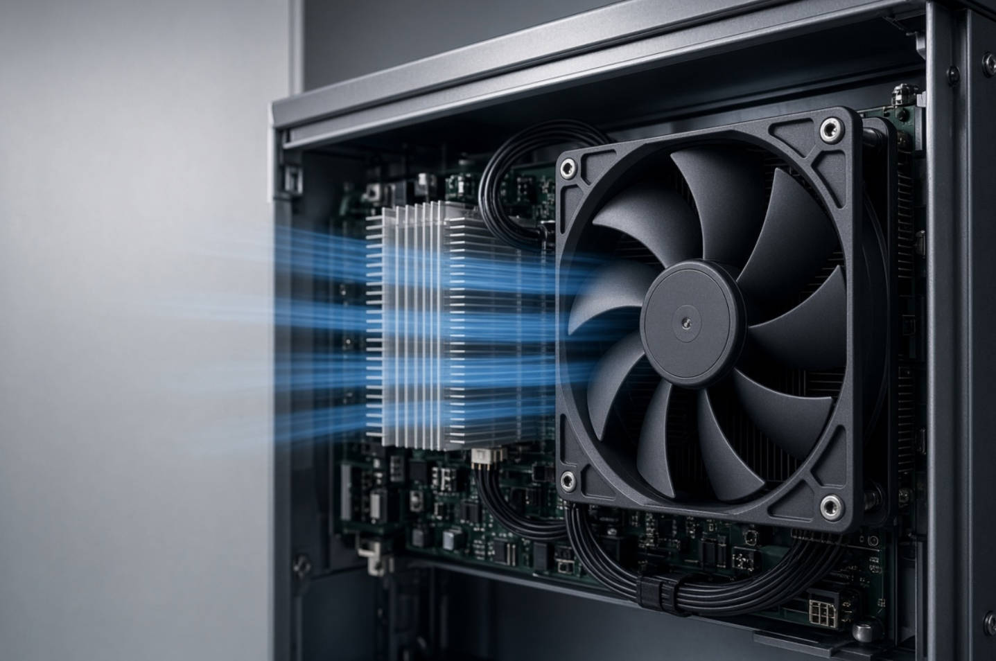
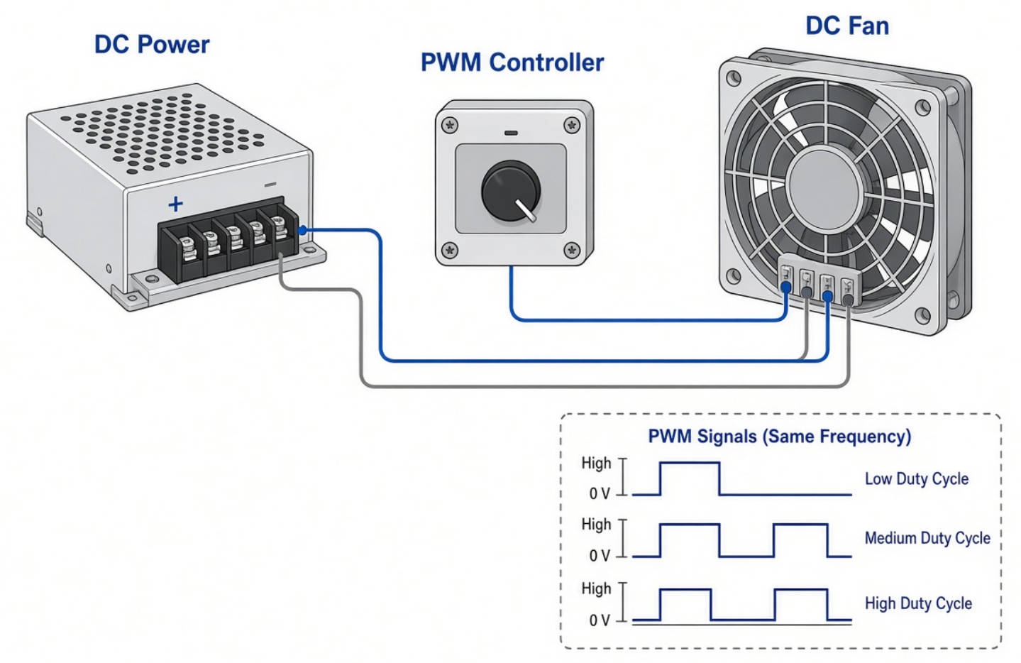
Pulse Width Modulation, or PWM, controls fan speed by changing the duty cycle of a pulse signal applied between the fan's control terminal and ground. The fan interprets that signal and adjusts its rotational speed according to its specified control characteristics.
Duty cycle describes the proportion of each signal period spent at the designated high level. However, a particular duty cycle does not guarantee the same speed across different fan models. The relationship between the input signal and rotational speed must come from the manufacturer's performance data.
A common selection mistake is treating 50% duty cycle as a universal command for 50% of maximum RPM.
SANYO DENKI's published example demonstrates why this assumption fails: at 60% duty cycle, one fan operates at 3,500 RPM while two others operate at 4,000 RPM. At 0%, one stops while the others continue at 1,500 RPM.
The essential selection document is therefore the duty-cycle-to-RPM curve. It reveals whether a fan's behavior actually matches the proposed controller and operating modes.
Check the control frequency and electrical signal requirements before connecting a fan. SANYO DENKI explicitly states that PWM input voltage and frequency differ between models.
Its controller lineup includes both 25 kHz and 1 kHz PCB models. Consequently, "PWM compatible" alone does not establish compatibility between a controller and a fan.
PWM control is a feature of a particular fan, not an automatic capability of every DC or AC product. For a PWM-input fan, the control terminal provides the external speed command described in the manufacturer's documentation.
Use the following distinctions during specification:
| Product category | Selection priority | Control question |
|---|---|---|
| DC fan with PWM input | Supply voltage, airflow, pressure, and control characteristics | Does the controller meet the documented input requirements? |
| DC fan without a documented PWM input | Supply and available control interfaces | What speed-control method does the manufacturer permit? |
| AC fan | AC supply requirements and documented control options | Does this exact model support external speed control? |
Treat this table as a specification checklist, not an interchangeability guide. A product's supply category does not, by itself, establish its control interface.
For mixed-product projects, document the supply connection and control connection separately. This helps prevent purchasing a mechanically suitable fan that cannot accept the intended speed command.
A system may require maximum cooling at peak load but much less airflow during standby or cooler operating periods. PWM control allows fan speed to follow these changing requirements instead of remaining permanently at maximum.
Noise reduction should nevertheless be evaluated in the finished equipment. Fan speed is only part of the acoustic result; operating point and airflow conditions also matter. AMCA's fan-noise guidance illustrates how acoustic performance changes with speed and operating conditions.
Fan affinity laws relate airflow approximately to speed, pressure to speed squared, and fan power to speed cubed under the relevant similarity assumptions.
For illustration, reducing speed to 80% gives a theoretical power ratio of:
0.8^3 = 0.512
That represents approximately 51.2% of the original aerodynamic power requirement—not a guaranteed electrical consumption figure for every installed DC fan. Motor efficiency, electronics, and operating conditions affect the actual result. Measure electrical input power when validating savings.
A thermistor and suitable controller can adjust PWM fan speed as equipment temperature changes. SANYO DENKI describes this arrangement as a way to regulate cooling in response to device or component temperatures.
The engineering objective is not the lowest possible fan speed. It is the lowest speed that still maintains acceptable temperatures under the tested operating conditions.
Do not select a cooling fan solely by its maximum free-air airflow.
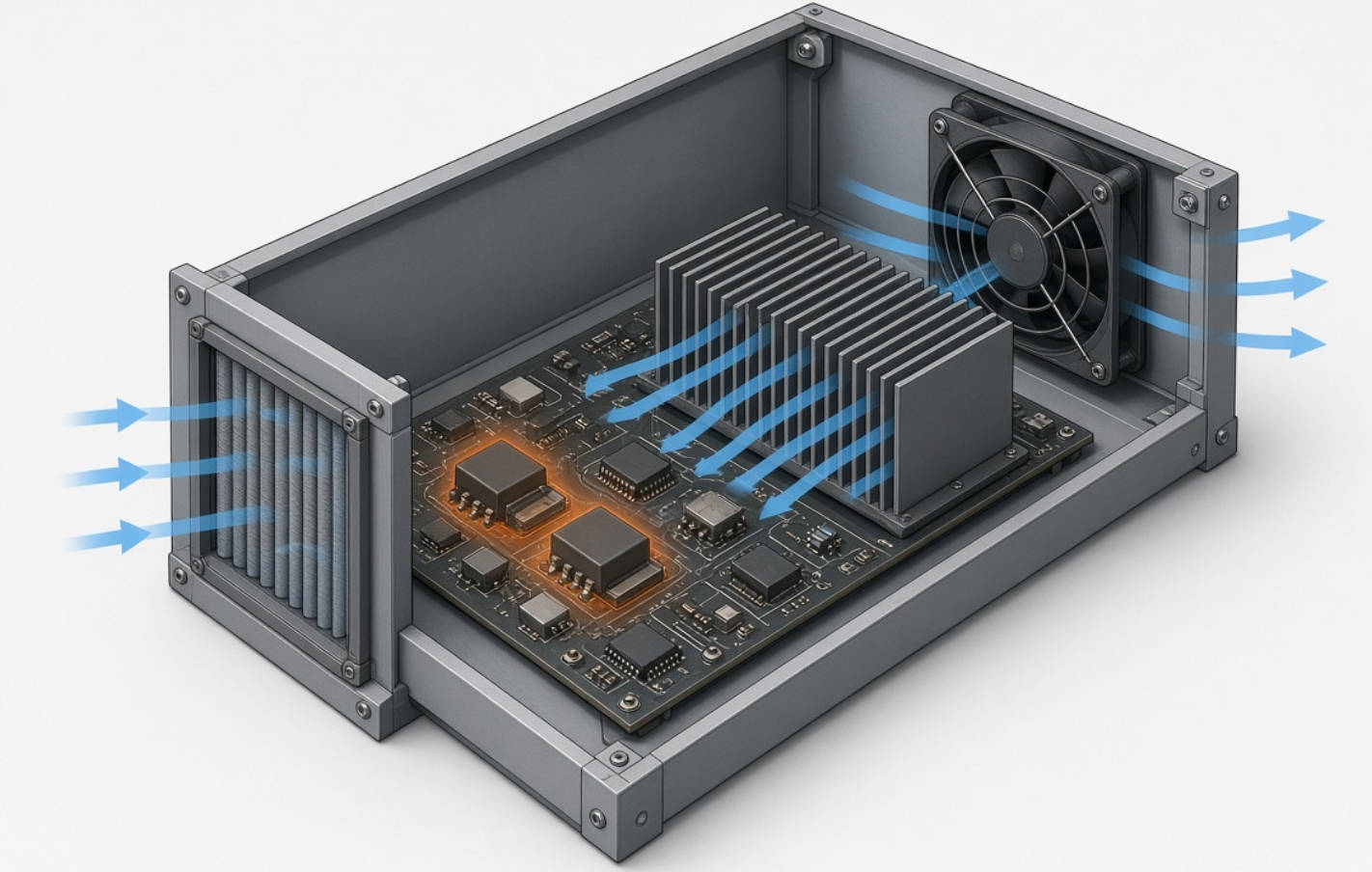
A fan must overcome the resistance of the actual enclosure and airflow path. The operating point depends on the relationship between the fan curve and system curve, which expresses the pressure required to move a given airflow through the system.
For an equipment-level review, identify:
- Heat-generating components and their temperature limits.
- Available inlet and outlet areas.
- Filters, heat sinks, and other airflow restrictions.
- Maximum specified ambient temperature.
- Mechanical size, mounting, and supply constraints.
Use those inputs to compare candidate fan curves before ordering evaluation samples.
The lowest duty cycle is not necessarily the lowest usable operating point.
In SANYO DENKI's illustrated example, the region below 20% duty cycle contains unstable-speed behavior. This is an example-specific characteristic, not a universal threshold for all PWM fans.
For each candidate, establish:
1. The minimum stable running duty cycle.
2. Whether 0% duty commands stop or continued rotation.
3. The conditions required for reliable restart.
4. The behavior when the control signal is absent.
Record these answers in the product specification rather than leaving them as assumptions.
A useful compatibility review includes:
| Parameter | What to confirm |
|---|---|
| Fan supply | Rated voltage and permitted operating range |
| PWM frequency | Required frequency for the selected model |
| Signal levels | Permitted high and low input levels |
| Driver interface | Manufacturer-specified output arrangement |
| Wiring | Control terminal, ground, and connector assignment |
| Controller loading | Number of fans and total permitted output load |
SANYO DENKI's controller documentation provides specific compatibility limits, including frequency, input-high voltage, and controller output capacity. Apply the limits for the exact model being purchased.
A workable control strategy needs more than a temperature reading and a continuously changing duty command. The following sequence provides a practical development framework based on the manufacturer's temperature-control approach and model-specific PWM characteristics.
Decide whether the controlled variable is an internal air temperature, a component-related measurement, or another validated thermal indicator.
A thermistor can detect air or component temperature, but those measurements serve different purposes. Document the sensor location and verify that it represents the condition the system must protect.
Create a preliminary schedule for standby, normal operation, and high-load operation.
Specify a duty cycle for each mode, then test the resulting RPM and temperatures. Do not derive the schedule by assuming that all fans share the same percentage-to-speed relationship.
As part of validation, test temperature changes around each transition point rather than only testing steady conditions.
Also establish acceptance criteria for sensor faults, fan stoppage, and loss of the control signal. These are project-specific requirements: the desired response must be checked against the selected fan and controller documentation.
A fan that remains stable at a low speed after startup may still need separate restart verification.
Include cold startup, restart after a commanded stop, and operation at the lowest intended duty cycle in the test plan. Approve the settings only after repeatable results.
SANYO DENKI's San Ace PWM Controller supports up to four compatible PWM-input fans and can use rated 12, 24, or 48 VDC fan power supplies. Available control methods vary by controller model.
This can simplify projects that otherwise require a newly designed control circuit.
However, a shared PWM signal does not guarantee identical RPM. SANYO DENKI's example shows different fans responding differently to the same duty cycle, including different behavior at 0%.
Before implementing shared control:
- Check every fan's electrical compatibility.
- Confirm the controller's total output limits.
- Compare each fan's duty-cycle-to-speed curve.
- Validate the combined cooling result.
- Document how fan failures will be detected.
A shared speed command should not be mistaken for independent monitoring of every connected fan.
SANYO DENKI's original article describes an outdoor surveillance-camera project with competing cooling and image-quality requirements. A high-performance video-processing engine generated substantial heat, but high-speed fan vibration contributed to image blurring.
The manufacturer reports that its proposed fans addressed vibration through structural design, balancing, and assembly accuracy. A PWM controller with thermistor-based regulation then allowed speed to follow thermal conditions.
The article quotes a customer reporting an additional 30 dB nighttime noise reduction. However, it does not publish enough measurement details to treat that figure as a generally reproducible expectation.
The useful lesson is broader than the reported number: evaluate thermal performance, vibration, and acoustics together. PWM control can adjust speed, but selecting an appropriate fan and validating its mechanical behavior remain essential.
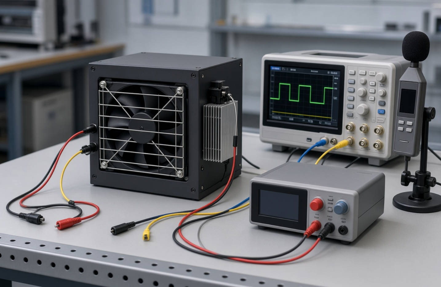
Use this checklist to convert a promising sample into an approved cooling configuration. It combines the source's model-specific control considerations with system-curve and power-measurement principles.
1. Inspect wiring, connector assignments, and supply requirements.
2. Confirm PWM frequency and signal levels.
3. Record RPM across the intended duty-cycle range.
4. Identify unstable operating regions.
5. Test stop and restart behavior.
6. Measure critical temperatures at representative loads.
7. Evaluate installed noise and vibration.
8. Measure fan electrical consumption.
9. Test the specified fault responses.
10. Retain the settings and results for production comparison.
Avoid approving a fan from one successful room-temperature test. The acceptance plan should reflect the equipment's specified operating envelope.
Capital Technology Co., Limited supplies DC fans, AC fans, and cooling solutions through our CAPITAL brand and SANYO DENKI offering. According to our company information, we serve customers including ZTE, HUAWEI, and HYTERA and act as SANYO DENKI's principal agent.
Send our team your supply voltage, available mounting space, airflow or pressure requirements, ambient-temperature range, noise targets, and intended control method.
Request a model-specific review and evaluation samples so your team can compare control compatibility and installed cooling performance before committing to volume procurement.
PWM means Pulse Width Modulation. A PWM-input fan uses the duty cycle of an external pulse signal to regulate rotational speed according to its specified characteristics.
No. SANYO DENKI shows an example in which one fan stops at 0% while others continue running. Check the exact model's specification.
No. PWM frequency requirements vary by model. SANYO DENKI's controller lineup includes both 25 kHz and 1 kHz products, so frequency compatibility requires verification.
Yes, within its documented limits. San Ace PWM controllers support up to four compatible fans, but identical input signals can produce different speeds on different models.
It can reduce fan consumption when lower speed still provides sufficient cooling. Fan laws explain the potential benefit, but actual electrical savings should be measured in the installed system.
Not by itself. The published camera case combines speed control with fan construction and balancing improvements. Evaluate vibration using the actual fan and mounting arrangement.
1. [SANYO DENKI — Features of Fans with PWM Control Function]. Primary source for operating examples, low-duty behavior, controller applications, and the surveillance-camera case. [techcompass.sanyodenki]
2. [SANYO DENKI — Fans with PWM Control: Technical Material]. Manufacturer guidance on PWM operation, model-specific input requirements, and temperature-responsive control. [products.sanyodenki]
3. [SANYO DENKI — PWM Controller Product Lineup]. Model-level controller information, including supply ratings, control functions, and frequency options. [products.sanyodenki]
4. [SANYO DENKI — San Ace PWM Controller Datasheet, hosted by Farnell]. Electrical compatibility, connection capacity, control options, and accessory requirements. [farnell]
5. [AMCA International — Fan and System Curves with Fan Energy Index]. Technical guidance on fan curves, system resistance, and operating points. [amca]
6. [AMCA International — Introducing the Fan Energy Index]. Background on fan energy performance and the relationship between speed and power. [amca]
7. [ANSI/AMCA 210 — Laboratory Methods of Testing Fans for Ratings, archived copy]. Reference for fan-law relationships and performance measurement concepts; cited for established principles, not as the latest edition. [law.resource]
8. [AMCA International — Basics of Fan Noise]. Technical background on acoustic behavior and operating conditions. [amca]
9. Capital Technology Co., Limited — company information supplied for this article. Source for the CAPITAL brand, business scope, stated agency relationship, and named customer relationships. No public supporting URL was supplied.


