From idea to market-ready product, our NPI solutions make every stage easier, faster. Discover How We Help
Help Center

Views: 295 Author: Capital Technology Publish Time: 2026-09-06 Origin: Site
Content Menu
● Why Cooling Fan Selection Matters in Electronic Equipment
● Start with a Thermal Design Brief
>> Key Questions to Answer Before Selecting a Fan
● Understand the Difference Between Airflow and Static Pressure
>> Airflow: How Much Air the Fan Moves
>> Static Pressure: The Fan's Ability to Overcome Resistance
● Choose Between DC Fans, AC Fans, and Blower Fans
>> DC Cooling Fans for Intelligent Thermal Control
>> AC Cooling Fans for Straightforward Mains-Powered Equipment
>> Blower Fans and Centrifugal Fans for Restrictive Systems
● Read Fan Curves Before Comparing CFM Ratings
>> How to Use a Fan Performance Curve
● Calculate Cooling Airflow from Heat Load
● Design the Airflow Path, Not Just the Fan Mounting
>> Best Practices for Electronic Enclosure Airflow
>> Example: Telecom Power Cabinet
● Select the Right Fan Size and Installation Format
● Evaluate Noise, Power Consumption, and Control Options
>> Important Acoustic Considerations
● Reliability, Bearing Choice, and Service Life
● A Practical Cooling Fan Selection Checklist
● Work with a Cooling Fan Supplier Early
>> 1. What is the difference between a DC fan and an AC fan?
>> 2. How do I calculate the required CFM for an electronics enclosure?
>> 3. Why does my fan deliver less airflow after installation?
>> 4. When should I choose a high-static-pressure fan?
>> 5. Is a bigger cooling fan always better?
>> 6. What is PWM fan control?
>> 7. How can I reduce cooling fan noise?
>> 8. How should I evaluate cooling fan life expectancy?
Selecting the right electronic equipment cooling fan is not simply a matter of choosing the highest CFM rating or the largest available size. A successful thermal design must match airflow, static pressure, voltage, noise, reliability, control method, installation space, and the real resistance inside the equipment enclosure.
For engineers designing telecom cabinets, industrial control systems, servers, power supplies, battery systems, EV charging equipment, medical devices, or communication hardware, the right DC fan or AC fan can protect component life, maintain stable performance, reduce maintenance risk, and improve the overall reliability of the finished product.
At Capital Technology Co., Limited, we support thermal-management projects with our independently developed CAPITAL cooling-fan brand as well as SANYO DENKI cooling-fan solutions. As an established supplier to customers including ZTE, HUAWEI, and HYTERA, we understand that fan selection is not a catalog exercise—it is an engineering decision that directly affects equipment uptime.
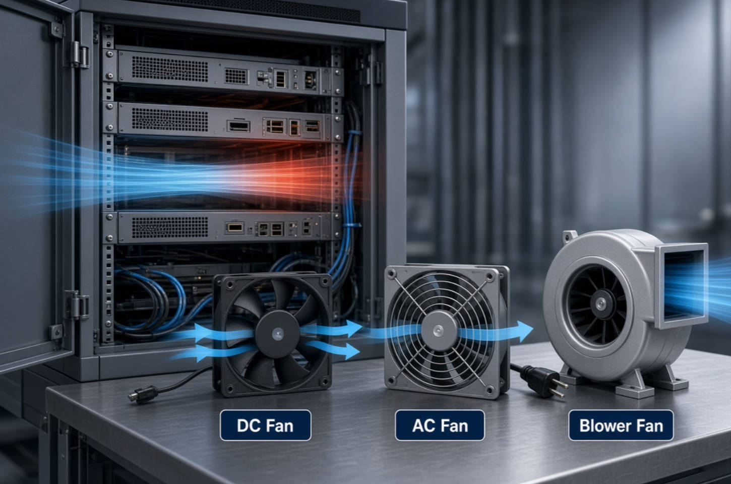
Electronic components convert part of their electrical energy into heat. CPUs, GPUs, MOSFETs, IGBTs, power modules, rectifiers, batteries, transformers, communication boards, and high-density connectors can all become heat sources. If that heat cannot leave the enclosure efficiently, the internal temperature rises.
Excessive temperature can lead to:
- Reduced electronic-component reliability
- Accelerated aging of capacitors, insulation, and solder joints
- Thermal throttling or performance instability
- Unplanned shutdowns and system alarms
- Higher maintenance costs
- Shortened product service life
- Increased risk of field failures in mission-critical equipment
A cooling fan creates forced airflow across heat-generating components and heat sinks. However, airflow only delivers meaningful cooling when it follows an effective path through the enclosure. A fan with an impressive free-air airflow rating may still underperform after it is installed behind filters, guards, grilles, heatsinks, cables, narrow ducts, or dense PCB assemblies.
That is why the best fan is not necessarily the fan with the highest rated airflow. The best fan is the one that achieves the required operating point in the actual system.
Before comparing DC cooling fans, AC cooling fans, blower fans, or high-static-pressure fans, define the operating requirements. This step prevents over-specification, under-cooling, unnecessary noise, and redesign delays.
Create a simple thermal design brief containing the following information:
| Selection Factor | Questions to Ask | Why It Matters |
|---|---|---|
| Heat load | How many watts of heat must the equipment remove? | Establishes the approximate cooling demand |
| Ambient temperature | What is the highest expected air temperature around the equipment? | Determines how much cooling capacity is realistically available |
| Target internal temperature | What maximum temperature can components safely tolerate? | Defines the thermal margin |
| Enclosure size | What mounting space, depth, inlet, and exhaust area are available? | Limits fan dimensions and airflow path options |
| Airflow resistance | Are there filters, grilles, ducts, heatsinks, or dense boards? | Determines required static pressure |
| Power source | Is the system powered by 12 VDC, 24 VDC, 48 VDC, 115 VAC, or 230 VAC? | Determines whether a DC fan or AC fan is appropriate |
| Noise target | Is the equipment located in an office, lab, hospital, factory, or outdoor cabinet? | Affects fan speed, blade design, control strategy, and acoustic specification |
| Operating environment | Will the fan face dust, humidity, vibration, salt mist, or high temperature? | Influences bearing, ingress protection, materials, and reliability requirements |
| Control requirements | Is PWM speed control, tachometer output, alarm signal, or remote monitoring needed? | Supports system intelligence and preventive maintenance |
A practical rule is to treat the fan as part of the complete thermal system rather than as an isolated component. The enclosure, vents, filters, cable routing, heat sinks, and board layout all influence final cooling performance.
Two specifications dominate cooling-fan selection: airflow and static pressure.
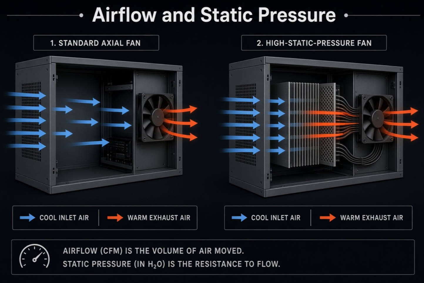
Airflow describes the volume of air moved by the fan over time. It is commonly expressed as:
- CFM — cubic feet per minute
- m³/h — cubic meters per hour
- m³/min — cubic meters per minute
A higher airflow value can be useful for relatively open equipment designs, such as cabinets with wide ventilation openings and a clear internal path from inlet to exhaust.
However, airflow values shown in a catalog are often measured under free-air conditions. In free air, the fan faces little or no resistance. That condition rarely represents a real electronic enclosure.
Static pressure describes the fan's ability to push air against resistance created by the system. It is often measured in:
- Pascal, or Pa
- Millimeters of water, or mmH₂O
- Inches of water gauge, or inH₂O
Restrictions inside an enclosure can include:
- Air filters
- Finger guards
- Protective grilles
- Dense heat-sink fins
- Narrow ventilation slots
- Ducting
- Cable bundles
- Closely packed circuit boards
- EMI shielding structures
- Dust accumulation over time
When static pressure rises, actual airflow falls. This relationship is shown by a fan performance curve, also called a P–Q curve. The fan's real operating point occurs where the fan curve meets the system-resistance curve.
In simple terms: high airflow is not enough if the air cannot pass through the system.
For example, an axial fan may provide strong free-air airflow in an open chassis. But if the same system includes a fine-pore filter, a restrictive grille, and a deep heat sink, a high-static-pressure DC fan or centrifugal blower may produce better real-world cooling.
SANYO DENKI explains that airflow is generally proportional to fan rotational speed, while static pressure is related to the square of rotational speed. This means increasing fan speed can significantly improve pressure capability, although it can also increase noise and power consumption.
The correct fan type depends on the available power supply, cooling requirements, enclosure resistance, control needs, and operating environment.
DC cooling fans are widely used in communication equipment, servers, battery systems, automation equipment, network switches, EV chargers, power supplies, and compact electronics.
Common DC voltages include:
- 5 VDC
- 12 VDC
- 24 VDC
- 48 VDC
DC fans are often preferred when a system needs precise speed control, lower-voltage operation, tachometer feedback, alarm output, or integration with a controller.
Advantages of DC fans include:
- Easy compatibility with low-voltage electronic systems
- PWM speed-control capability
- Tachometer and locked-rotor signal options
- Lower fan speed during light-load conditions
- Reduced noise and energy use when controlled properly
- Better support for smart thermal-management strategies
A PWM-controlled DC fan can automatically increase speed when a temperature sensor detects rising internal temperature. When the equipment runs at a lower thermal load, the controller can reduce fan speed to lower acoustic noise and power consumption.
This is particularly valuable in telecom base stations, data-network equipment, energy-storage systems, and industrial automation cabinets where operating conditions vary throughout the day.
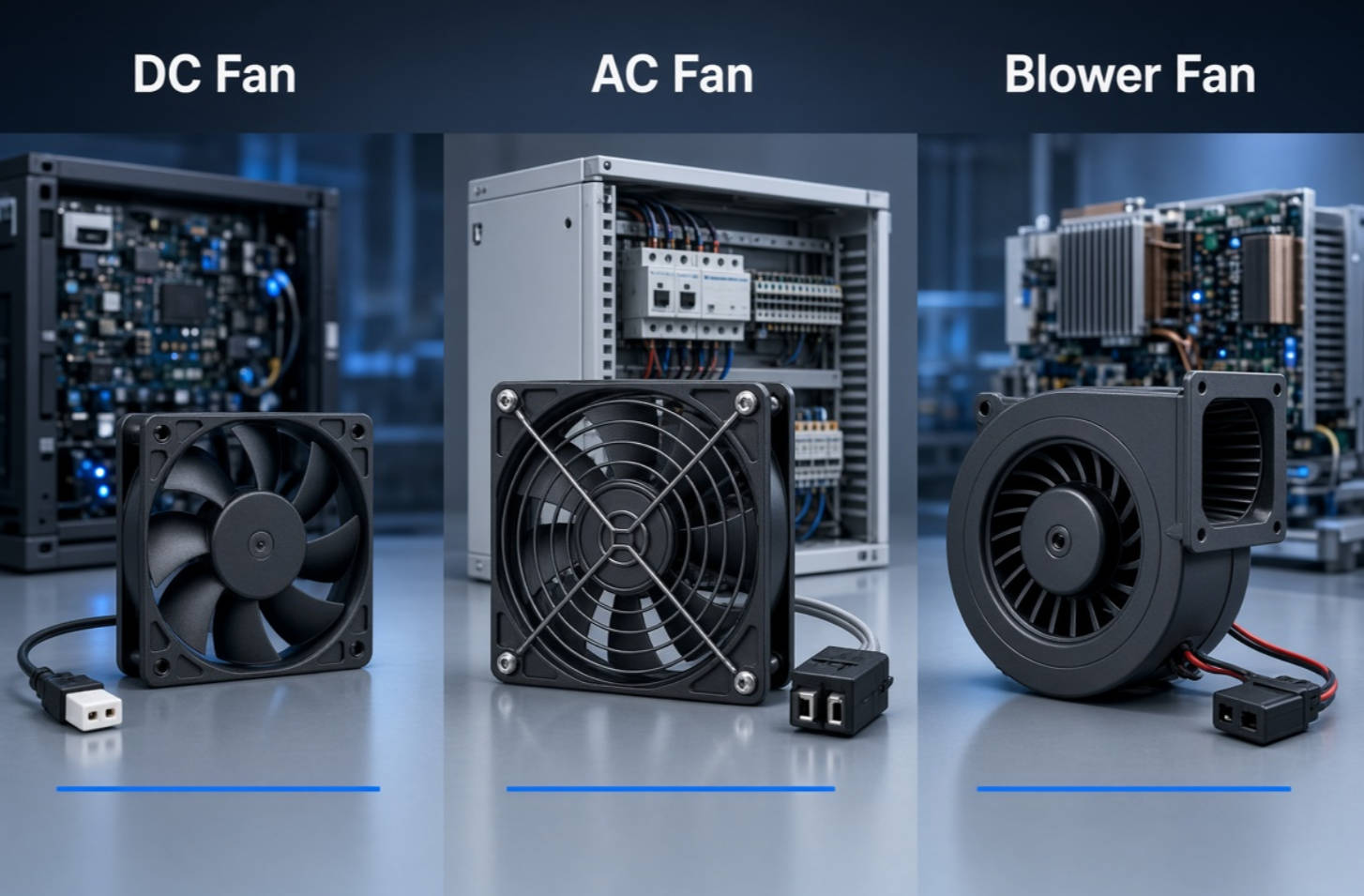
AC cooling fans are commonly used in equipment with direct AC power input, including industrial cabinets, control panels, machinery, welding equipment, power distribution equipment, HVAC-related electronics, and general-purpose electrical enclosures.
Common AC supply options include:
- 115 VAC
- 220 VAC
- 230 VAC
- 50/60 Hz operation
AC axial fans are often selected because they provide a straightforward cooling solution for systems that do not require advanced electronic speed control. They can be practical for stable, continuous-duty industrial applications where reliability and simple installation are priorities.
Typical advantages include:
- Direct connection to AC power systems
- Simple installation and wiring
- Suitable for many industrial cabinets
- Broad availability in common frame sizes
- Practical choice for constant-speed cooling applications
When choosing an AC fan, verify the local voltage and frequency requirements. A mismatch between 50 Hz and 60 Hz performance can affect speed, airflow, power consumption, and noise.
A blower fan or centrifugal fan moves air in a direction perpendicular to the intake flow. Instead of pushing air straight through the fan axis, it generates airflow through a scroll-shaped housing or blower configuration.
Blower fans are often the better option when an application has high airflow resistance, narrow ducts, compact channels, or concentrated heat sources.
Consider a blower fan when your system includes:
- Long or narrow ducts
- High-density heat sinks
- Tight airflow channels
- High-resistance filters
- Compact medical devices
- Laser equipment
- Battery modules
- Power electronics
- Enclosures with limited vent area
Axial fans are often efficient in more open environments, while centrifugal or blower designs are typically better suited to applications requiring stronger pressure performance.
A fan datasheet should never be evaluated using airflow alone. The performance curve provides the real basis for selection.
A typical fan curve plots:
- Horizontal axis: Airflow
- Vertical axis: Static pressure
- Curve: The fan's available pressure at each airflow level
At zero static pressure, the fan produces its maximum free-air airflow. At zero airflow, the fan reaches its maximum static pressure. Neither point usually represents the normal operating condition inside equipment.
The actual operating point depends on your system resistance.
1. Estimate the system airflow requirement based on heat load and allowable temperature rise.
2. Identify restrictions such as filters, grilles, ducts, heatsinks, and cable congestion.
3. Estimate or test the system static pressure at the desired airflow.
4. Locate the intersection of required airflow and static pressure.
5. Select a fan whose curve provides sufficient margin at that operating point.
6. Validate the design with prototype thermal testing under worst-case conditions.
According to ebm-papst, static pressure represents the resistance to airflow created by factors such as turbulence, filters, grilles, and other internal impedances. As static pressure increases, airflow decreases.
Do not select a fan at the extreme end of its performance curve unless there is a strong engineering reason. Operating too close to the limit can make the system sensitive to dust buildup, manufacturing variation, changing ambient conditions, or future product revisions.
A simplified airflow calculation can provide an initial fan-sizing estimate. For air cooling, a commonly used engineering approximation is:
Airflow (CFM)≈(3.16×Heat Load (W))/Allowable Temperature Rise (°C)
For example, if an enclosure produces 300 W of heat and the design permits a 10°C rise between inlet and outlet air:
Airflow≈(3.16×300)/10=94.8 CFM
This result is only a starting point. It does not account for:
- Uneven heat distribution
- Hot spots around processors or power modules
- Airflow bypassing critical components
- Pressure losses through filters and grilles
- Reduced performance at high altitude
- Dust loading over time
- Fan aging
- Recirculation of hot exhaust air
For this reason, use the calculation to create an initial thermal design, then confirm it with physical testing, CFD simulation, or both.
A strong cooling fan cannot compensate for a poor enclosure airflow path. The goal is to bring cooler air to heat-producing components and remove hot air without allowing it to recirculate.

- Place the air inlet near the lowest-temperature air source.
- Position exhaust openings where hot air naturally accumulates, often near the top or rear of the enclosure.
- Create a clear inlet-to-exhaust path across the most critical heat sources.
- Avoid placing fans where air immediately short-circuits from inlet to outlet.
- Keep cable bundles from blocking vents or heatsink channels.
- Use baffles or ducting to direct air through high-heat zones.
- Ensure inlet and exhaust vent areas are adequate for the intended airflow.
- Allow maintenance access for filters and fan replacement.
- Consider redundant fans for critical equipment.
- Test the system after filters accumulate realistic dust loading.
A common mistake is positioning the cooling fan close to an exhaust vent without guiding airflow across the PCB or heat sink. In that situation, the fan may move plenty of air, but it may bypass the components that actually need cooling.
Consider a telecom power cabinet containing rectifiers, DC/DC converters, control boards, and battery-management components. A basic open-frame axial fan might have adequate CFM on paper, yet the cabinet also contains EMC shielding, filters, wiring harnesses, and narrow internal channels.
A stronger high-static-pressure DC fan may deliver better thermal results because it can maintain airflow despite these restrictions. If the system has variable traffic or power demand, PWM control can reduce fan speed during low-load periods and increase speed during peak operation.
This approach can improve thermal performance without operating at maximum noise all the time.
Cooling fans come in many dimensions and thicknesses. Common axial fan frame sizes include:
- 40 mm × 40 mm
- 50 mm × 50 mm
- 60 mm × 60 mm
- 80 mm × 80 mm
- 92 mm × 92 mm
- 120 mm × 120 mm
- 172 mm × 172 mm
- 200 mm × 200 mm
- 250 mm × 250 mm
Fan thickness also matters. A thicker fan can often provide better static-pressure performance than a thinner fan of the same frame size, although actual performance depends on blade geometry, motor design, speed, and overall construction.
Before selecting a model, verify:
- Mounting-hole spacing
- Overall depth
- Clearance for connectors and wire exit
- Airflow direction
- Fan guard compatibility
- Filter compatibility
- Vibration-isolation requirements
- Orientation limitations
- Weight and structural support
- Service access for replacement
Larger fans can often move the same airflow at lower RPM, which may help reduce noise. However, larger is not always better when space is limited or when pressure resistance is high.
Cooling performance must be balanced against acoustics and energy use. In office, medical, laboratory, broadcasting, residential, and customer-facing equipment, fan noise can become a major product-quality issue.
Fan noise is typically measured in dBA. But the dBA value alone does not tell the complete story. The perceived quality of fan noise also depends on tonal characteristics, vibration, resonance, airflow turbulence, and the operating environment.
To reduce noise:
- Avoid oversizing the fan speed unnecessarily.
- Use PWM or voltage control where appropriate.
- Choose a larger, slower fan when enclosure space allows.
- Reduce sharp airflow restrictions near the fan inlet and outlet.
- Use properly designed finger guards and grilles.
- Avoid mounting fans against obstructive surfaces.
- Isolate vibration if enclosure resonance is a concern.
- Keep blades, filters, and vents clean.
PWM control can be especially effective because fan speed can follow actual thermal demand. SANYO DENKI notes that PWM-controlled fan products enable speed adjustment and can contribute to lower noise and improved device energy efficiency.
A cooling fan is a moving component, so reliability must be considered as carefully as airflow.
The operating life of a fan can be affected by:
- Ambient temperature
- Motor temperature
- Bearing type
- Dust and contamination
- Humidity
- Vibration and shock
- Fan orientation
- Voltage quality
- Continuous or intermittent operation
- Speed-control profile
- Maintenance conditions
Fan manufacturers may state expected life using an L10 life specification. L10 typically indicates the operating time at which 90% of a sample population is expected to remain functional under defined test conditions.
For example, SANYO DENKI has published products with 40,000-hour and 100,000-hour L10 life ratings under specified continuous-operation conditions, including rated voltage and 60°C free-air environments. These values should be interpreted carefully because real-life conditions may differ significantly from laboratory test conditions.
When comparing fan life data, always ask:
- Under what temperature was life tested?
- Was the fan operating in free air or inside a restrictive enclosure?
- What voltage was applied?
- What survival-rate definition was used?
- Does the bearing system suit the orientation and vibration level?
- Will dust, humidity, or corrosive contaminants shorten field life?
For telecom, transportation, industrial automation, outdoor cabinets, and other high-uptime applications, selecting a reliable fan and designing for easy replacement can be more valuable than choosing the lowest initial-cost option.
Use this checklist before approving a DC fan, AC fan, or blower fan for production:
1. Define the total heat load in watts.
2. Identify the highest ambient operating temperature.
3. Set the allowable internal temperature rise.
4. Estimate the required airflow.
5. Map the enclosure's airflow path.
6. Identify pressure losses from filters, grilles, heat sinks, ducts, and boards.
7. Select axial or centrifugal airflow based on resistance.
8. Choose DC or AC voltage based on the system power architecture.
9. Check the fan curve at the real operating point.
10. Confirm size, thickness, mounting pattern, and airflow direction.
11. Review noise requirements and control options.
12. Evaluate bearing, expected life, temperature range, and environmental resistance.
13. Consider alarm output, PWM control, tachometer feedback, or redundancy.
14. Build a prototype and test temperatures at maximum load and worst-case ambient conditions.
15. Validate performance after adding guards, filters, cables, and production hardware.
The best time to involve a cooling-fan supplier is during the product-design stage, not after the enclosure, PCB layout, and ventilation openings have already been finalized.
Early technical review can help identify:
- Inadequate inlet or exhaust vent area
- Poor fan placement
- Excessively restrictive filters or grilles
- Hot-spot risk near power devices
- Opportunities for quieter fan operation
- Whether a DC fan, AC fan, or blower fan is the better choice
- Appropriate fan control, alarm, and redundancy strategies
- Suitable fan models for OEM production and long-term supply
Capital Technology Co., Limited provides cooling-fan solutions for customers requiring dependable DC fans, AC fans, high-static-pressure fans, and application-oriented thermal support. With the CAPITAL brand and access to SANYO DENKI fan solutions, our team can help evaluate fan performance, voltage, dimensions, airflow direction, static-pressure requirements, noise targets, and expected operating conditions.
Need help selecting the right electronic equipment cooling fan? Contact Capital Technology Co., Limited with your heat load, enclosure drawing, supply voltage, operating temperature, airflow path, and target service life. Our engineering team can help you shortlist a practical DC fan, AC fan, or blower solution for your application.
A DC fan operates from direct-current power, such as 12 VDC, 24 VDC, or 48 VDC. It is commonly used in electronic equipment because it can support PWM speed control, tachometer feedback, alarm output, and intelligent thermal management. An AC fan operates from alternating-current power, such as 115 VAC or 230 VAC, and is commonly used in industrial equipment and electrical cabinets that have direct AC power available.
A basic estimate is:
CFM≈ (3.16×Heat Load in Watts)/Allowable Temperature Rise in °C
Use this as a starting point only. The final fan selection must account for static pressure, filters, grilles, heat sinks, cable congestion, airflow bypass, high ambient temperature, and prototype-test results.
The rated airflow on a datasheet is often measured in free air. After installation, filters, finger guards, grilles, ducts, heatsinks, narrow vents, and internal components create static pressure. Higher static pressure reduces actual airflow. Review the fan's P–Q curve and select a fan with sufficient pressure capability for the real system resistance.
Choose a high-static-pressure fan when air must move through restrictive paths. Typical examples include dense server equipment, telecom cabinets, filter-equipped enclosures, high-fin-density heat sinks, power electronics, compact battery systems, and ducted cooling paths.
No. A larger fan may move more air at lower speed and lower noise, but it may not fit the enclosure or provide sufficient static pressure for a restrictive design. The right fan must match available space, voltage, airflow requirement, pressure resistance, noise target, and reliability expectation.
PWM, or pulse-width modulation, is a method for controlling a compatible DC fan's speed. A controller adjusts the PWM signal according to temperature or system load. This allows the fan to run more quietly and use less power during light-load conditions while increasing cooling capacity when temperatures rise.
Use a fan that meets the real airflow and pressure requirement without excessive speed. Improve inlet and exhaust design, reduce grille and filter restrictions, use PWM control, avoid turbulent airflow near the fan, keep filters clean, and consider a larger fan operating at a lower RPM when the enclosure permits it.
Review the manufacturer's life-rating method, test temperature, applied voltage, operating environment, bearing type, and L10 definition. Then compare those conditions with your real application, including ambient temperature, dust, vibration, humidity, orientation, and maintenance practice.
1. Sofasco. "How to Choose the Right Electronic Equipment Cooling Fans for Your Applications?" [Read the original article]
2. SANYO DENKI Tech Compass. "Basic Knowledge for Selecting a Cooling Fan." [Read the fan-selection guide]
3. SANYO DENKI Tech Compass. "Fan Airflow and Static Pressure." [Read the airflow and static-pressure guide]
4. SANYO DENKI Tech Compass. "Fan Lifespan." [Read the fan-life guide]
5. SANYO DENKI. "60 × 38 mm 9HVA Type High Static Pressure Fan Released." [Read the product announcement]
6. SANYO DENKI. "40 × 40 × 28 mm Long Life Fan with the Highest Static Pressure." [Read the long-life fan announcement]
7. ebm-papst. "FAQ: Airflow, Static Pressure, and Fan Performance Curves." [Read the technical FAQ]
8. ebm-papst. "Axial Compact Fans." [Read the axial-fan overview]


