From idea to market-ready product, our NPI solutions make every stage easier, faster. Discover How We Help
Help Center

Views: 241 Author: Capital Technology Publish Time: 2026-10-16 Origin: Site
Content Menu
● High Airflow vs High Static Pressure Fans: Key Differences
>> What Does High Airflow Mean?
>> What Does High Static Pressure Mean?
● Why the Pressure–Airflow Curve Matters More Than Maximum CFM
>> How System Resistance Changes Fan Performance
>> Why a Lower-CFM Fan Can Deliver Better Installed Cooling
● When Should You Choose a High-Airflow San Ace Fan?
>> Check Air Distribution, Not Just Air Volume
● When Should You Choose a High-Static-Pressure San Ace Fan?
>> Pressure Capability Is Not Permission to Ignore Noise
● Real San Ace Specifications: What the Numbers Actually Tell You
>> What the 2024 San Ace 38 Release Adds
● A Practical Five-Step Fan Selection Process
>> 1. Define the Thermal Requirement
>> 2. Establish the Actual Airflow Path
>> 3. Measure or Estimate System Impedance
>> 4. Compare Candidate Curves
>> 5. Validate the Finished Equipment
● Two Often-Missed Design Checks
>> Filter Loading Can Change the Right Fan Choice
>> Installation Changes Can Outweigh a Fan Upgrade
● How CAPITAL Supports San Ace Fan Selection
>> 1. Are High-Airflow Fans and High-Static-Pressure Fans Different Technologies?
>> 2. Can I Use a High-Static-Pressure Fan in an Open Enclosure?
>> 3. Is Maximum Static Pressure the Pressure Available at Maximum Airflow?
>> 4. Which San Ace Fan Is Best for a Filtered Telecom Cabinet?
>> 5. Does PWM Control Remove the Need for Pressure-Based Selection?
>> 6. Are These Selection Principles Different for AC Fans?
Choosing between high airflow vs high static pressure fans starts with one question: how difficult is it for air to move through your equipment? A high-airflow fan suits an open, low-resistance enclosure. A high-static-pressure fan is generally the better starting point for dense heatsinks, filters, narrow ducts, and tightly packed electronics.
However, these are performance priorities—not mutually exclusive fan categories. Many San Ace fans deliver both substantial airflow and high pressure capability.
My recommendation is to select around the operating point: the airflow a fan actually delivers against your equipment's resistance. That matters more than the largest number in a product table.
This guide explains the differences, compares documented San Ace specifications, and provides a practical selection process for engineers and purchasing teams.

Airflow describes how much air a fan moves. Static pressure describes the pressure difference it can develop to overcome resistance.
Both determine cooling performance, but their importance changes with the installation.
| Selection factor | Airflow-focused selection | Static-pressure-focused selection |
|---|---|---|
| Main objective | Move substantial air through an open path | Maintain sufficient airflow through restrictions |
| Typical installation | Spacious enclosure with generous ventilation | Dense electronics, restrictive heatsinks, filters, or ducts |
| Critical comparison | Delivered airflow at low resistance | Delivered airflow at the required pressure |
| Common purchasing mistake | Treating maximum airflow as installed airflow | Assuming maximum pressure guarantees better cooling |
| Essential verification | Enclosure airflow and component temperatures | Pressure–airflow curve and component temperatures |
Neither approach eliminates the other requirement. A pressure-capable fan still needs enough airflow to remove heat. An airflow-focused fan still needs sufficient pressure capability for its actual installation.
Airflow is commonly expressed in cubic feet per minute, or CFM, and cubic meters per minute, or m³/min.
A fan's maximum airflow normally represents operation near zero static pressure. This is a useful reference, but it does not describe performance behind a filter or inside a crowded enclosure.
High airflow is especially valuable when the cooling path offers little resistance and the design needs to exchange a large volume of air.
Static pressure is commonly expressed in pascals, or Pa, and inches of water.
A fan's maximum static pressure occurs at essentially zero airflow. It represents pressure capability—not a useful cooling condition by itself.
This distinction is important: maximum airflow and maximum static pressure are opposite endpoints of the performance curve. They do not occur simultaneously.
A fan's pressure–airflow curve, often called its P–Q curve, shows how airflow changes as pressure requirements increase.
Your equipment has a separate resistance characteristic, called its system impedance curve. The intersection of these curves determines the operating point.
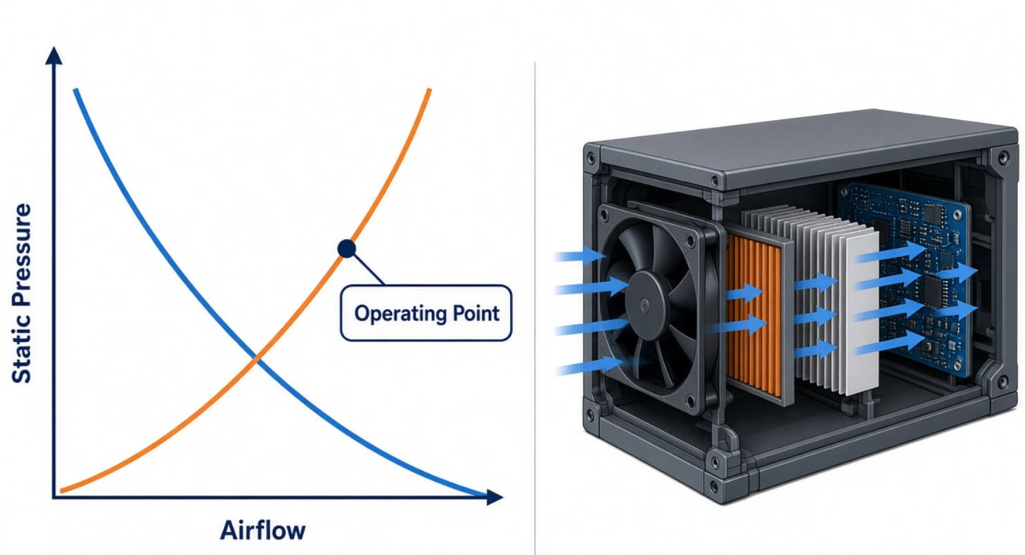
Filters, grilles, heatsinks, circuit boards, cables, and ducts all contribute to resistance.
For a fixed airflow path, engineers often approximate this relationship as:
ΔP=KQ2
Here, ΔP is pressure loss, Q is airflow, and K represents system resistance. This is a useful approximation, not a substitute for measurement.
As resistance increases, the operating point generally shifts toward lower airflow.
That explains why a fan with an impressive free-air rating can disappoint after installation. Its specification may be correct; the selection simply overlooked the enclosure.
Consider two hypothetical fans:
- Fan A has the higher maximum airflow.
- Fan B has the stronger pressure capability.
- At your equipment's required pressure, Fan B delivers more airflow.
Fan B may therefore provide better cooling in that installation despite its lower maximum-CFM rating.
The reverse can happen in an open enclosure. Compare complete curves at the expected operating condition rather than ranking fans by one endpoint.
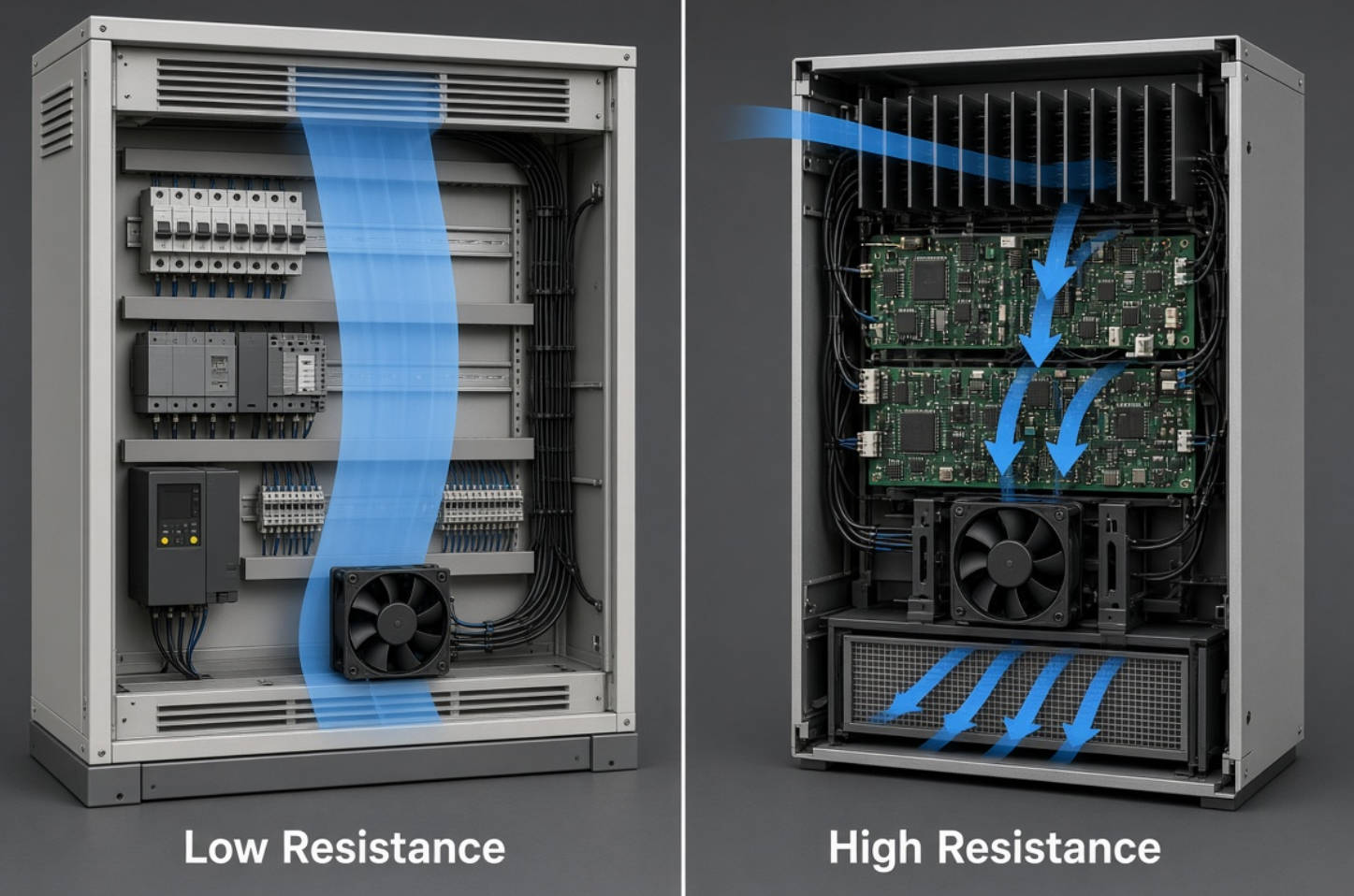
Start with airflow-focused selection when your equipment provides a relatively unobstructed route from intake to exhaust.
Typical examples include:
- Spacious industrial control cabinets.
- Open electronic assemblies.
- Equipment with large ventilation openings.
- Low-density enclosures without restrictive filters.
- Applications requiring broad enclosure air exchange.
The key condition is low resistance, not simply a large cabinet.
A spacious enclosure can still need substantial pressure capability if air must pass through a small filter, restrictive grille, or narrow internal passage.
Large airflow does not guarantee that air reaches the hottest component.
Air can bypass a heatsink or recirculate between the exhaust and intake. Before specifying a faster fan, examine component placement, vent locations, and possible bypass paths.
Sometimes improving the airflow route is more effective than increasing the fan rating.
Prioritize pressure capability when the cooling path contains significant restrictions.
Common applications include:
- Dense server and storage equipment.
- Telecom and networking hardware.
- Power supplies with closely packed components.
- Narrow heatsink fin passages.
- Filtered industrial enclosures.
- Compact equipment with constrained ventilation.
SANYO DENKI identifies high-density servers, storage devices, switching power supplies, and communications equipment among the applications for specific San Ace high-static-pressure models.
Still, application labels only provide a starting point. Two telecom products can have very different resistance characteristics.
High pressure performance can involve high rotational speeds and substantial power consumption. However, noise cannot be predicted from a category label alone.
Compare candidate models at the speed and operating condition your equipment actually requires.
A powerful fan running under controlled speed may be appropriate, but its acoustic behavior must be verified in the finished assembly.
The following published examples illustrate the relationship between airflow, pressure, size, and power.
These are not interchangeable recommendations or a controlled comparison between identical-size fans.
| San Ace model | Dimensions | Rated voltage | Maximum airflow | Maximum static pressure | Rated input |
|---|---|---|---|---|---|
| 9HV0912P4G001 | 92 × 92 × 25 mm | 12 VDC | 118 CFM | 280 Pa | 14.76 W |
| 9HVA0612P1J001 | 60 × 60 × 38 mm | 12 VDC | 84.3 CFM | 2,000 Pa | 33.6 W |
| 9HVA0312P3K001 | 38 × 38 × 28 mm | 12 VDC | 32.2 CFM | 2,100 Pa | 25.2 W |
The larger 92 mm model has the highest maximum airflow in this table. The smaller models provide substantially higher maximum pressure.
However, none of these endpoint figures tells you which fan will deliver the most useful airflow in your particular equipment.
The 38 × 38 × 28 mm 9HVA model, announced in October 2024, combines 32.2 CFM maximum airflow with 2,100 Pa maximum static pressure.
Its significance is not that every compact device needs this performance. It demonstrates that compact dimensions do not automatically mean low pressure capability.
Before choosing it, check its complete curve, electrical requirements, noise, and suitability for the intended environment.
Record the equipment's heat dissipation, maximum inlet temperature, permissible temperature rise, and critical component limits.
An initial airflow estimate can use:
Q=P/ρcpΔT
Here, Q is volumetric airflow, P is the heat transferred to the air, ρ is air density, and cp is specific heat capacity.
This estimates bulk airflow requirements. It does not predict individual component hotspots.
List every significant restriction, including filters, guards, heatsinks, internal partitions, and outlet openings.
Evaluate the assembled enclosure rather than an empty chassis. Small mechanical changes can alter resistance and air distribution.
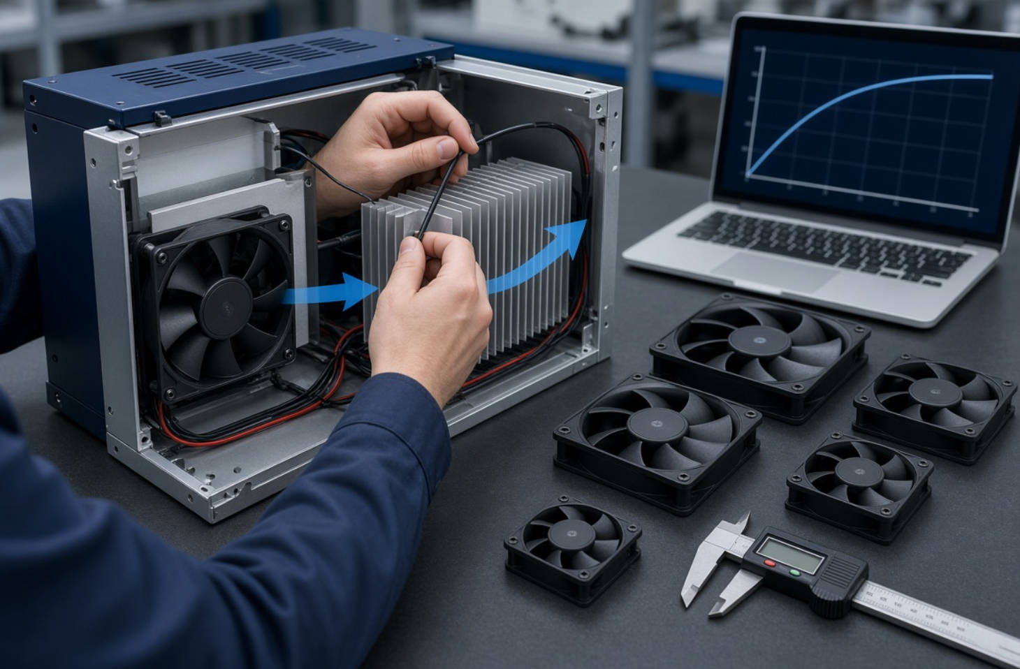
Use measurement where possible.
The San Ace Airflow Tester is designed to measure system impedance and operating airflow, providing a stronger basis for selection than maximum-CFM comparisons.
If measurement is unavailable, use preliminary estimates cautiously and make installation testing part of the development plan.
Identify fans that deliver the required airflow at the expected pressure.
Then compare:
- Power consumption.
- Sound pressure level.
- Voltage range.
- Dimensions and mounting.
- Speed-control and monitoring functions.
- Environmental and service-life requirements.
Check the exact model number. Models within the same family can have different speeds, wiring, and performance.
Test with the intended filter, grille, wiring, covers, and component arrangement.
Measure critical component temperatures alongside inlet and exhaust conditions. Where relevant, evaluate maximum thermal load and foreseeable filter loading.
Passing a free-air bench test does not establish performance inside the final product.
A clean filter represents only one operating condition.
As contamination accumulates, resistance can increase and airflow can fall. For filtered equipment, define an acceptable maintenance condition and verify that cooling remains adequate within it.
This is more useful than adding an arbitrary percentage to maximum airflow. The margin should address an identifiable operating risk.
Before moving to a more powerful fan, review:
- Undersized intake or exhaust openings.
- Cables crossing the airflow path.
- Air leakage around the heatsink.
- Exhaust air returning to the intake.
- Unnecessary restrictions close to the fan.
Reducing resistance may allow the required cooling at lower speed. It can also prevent spending more on a fan while leaving the underlying airflow problem unresolved.
Capital Technology Co., Limited manufactures DC and AC cooling solutions under its CAPITAL brand and serves as SANYO DENKI's chief agent. Its customer background includes supplying ZTE, HUAWEI, and HYTERA.
For buyers, this combination creates a useful starting point for discussing both equipment requirements and available fan options.
However, supplier experience does not replace application validation. A suitable recommendation still depends on the exact enclosure, heat load, electrical interface, and operating environment.
When requesting a selection review, provide:
1. Available fan dimensions and mounting details.
2. Supply voltage and electrical limits.
3. Heat load and temperature targets.
4. Enclosure drawings or airflow-path photographs.
5. Filters, heatsinks, grilles, and duct details.
6. Noise, control, monitoring, and environmental requirements.
Send these details to CAPITAL to request a San Ace shortlist and the relevant performance curves. Ask which candidate meets your required airflow at the expected system pressure—not simply which model has the highest CFM.
Not necessarily. The terms describe performance priorities rather than completely separate technologies. A San Ace fan can provide both high airflow and substantial pressure capability. Compare the full curve instead of relying on the category name.
Yes, if its electrical, mechanical, acoustic, and airflow characteristics suit the application. However, buying additional pressure capability may offer little benefit when system resistance is low. Select for the actual operating requirement.
No. Maximum static pressure occurs near zero airflow, while maximum airflow occurs near zero static pressure. The fan's performance curve shows the combinations available between these endpoints.
There is no universal model. Filter resistance, enclosure layout, heat load, voltage, noise limits, and maintenance conditions all affect selection. Begin with the required operating airflow and compare suitable models at the expected pressure.
No. PWM allows external speed control on models equipped with that function, but it does not remove airflow restrictions. The selected fan must still provide sufficient airflow against system resistance at the required control condition.
The aerodynamic principles remain the same: evaluate airflow, pressure, system resistance, and the installed operating point. AC and DC products differ in their electrical supply and available control arrangements, so verify those requirements separately.
1. SANYO DENKI. "Guideline in Selecting a Fan." Manufacturer guidance on airflow estimation, system impedance, pressure–airflow characteristics, and final installation testing. Supports the thermal-sizing and selection methodology. [products.sanyodenki]
2. SANYO DENKI. "San Ace Airflow Tester." Technical Report No. 42, 2016. Explains system-impedance measurement, quadratic resistance curves, operating points, and comparison of candidate fans by noise and power consumption. [sanyodenki]
3. SANYO DENKI. "Airflow Tester." Product overview describing measurement of equipment system impedance, operating airflow, and pressure–airflow performance. [products.sanyodenki]
4. SANYO DENKI. "SANYO DENKI Launches 92 × 92 × 25 mm High Static Pressure Fan." November 4, 2020. Source for model 9HV0912P4G001 dimensions, voltage, airflow, static pressure, and rated input. [sanyodenki]
5. SANYO DENKI. "60 × 38 mm 9HVA Type High Static Pressure Fan Released." April 1, 2022. Source for model 9HVA0612P1J001 specifications and stated high-density server and storage applications. [sanyodenki]
6. SANYO DENKI. "38 × 38 × 28 mm San Ace 38 9HVA Type DC Fan." October 9, 2024. Source for model 9HVA0312P3K001 specifications and release information. [sanyodenki]
7. SANYO DENKI. "San Ace 40 9HVA Type High Static Pressure Fan." May 28, 2020. Documents applications including 1U servers, switching power supplies, and communications equipment. [sanyodenki]
8. SANYO DENKI. "40 × 40 × 28 mm High Static Pressure Fan San Ace 40 9HVA Type." Technical development report discussing impeller, frame, motor, speed, and PWM control. [sanyodenki]


