From idea to market-ready product, our NPI solutions make every stage easier, faster. Discover How We Help
Help Center

Views: 275 Author: Capital Technology Publish Time: 2026-08-20 Origin: Site
Content Menu
● Duct Fan vs. Axial Fan: Quick Comparison
● Airflow and Static Pressure Explained
>> 2. Calculate System Resistance
>> 3. Compare Fan Curves at the Duty Point
>> 4. Consider Noise and Control
● Installation Errors That Reduce Fan Performance
● Practical Application Example
● Why Engineering Support Matters
● FAQ
>> 1. What is the main difference between a duct fan and an axial fan?
>> 2. Can an axial fan be installed in ductwork?
>> 3. Are duct fans always quieter than axial fans?
>> 4. How do filters affect fan selection?
>> 5. Which fan type is better for telecom cabinets?
>> 6. How can I reduce fan energy consumption?
Choosing between a duct fan and an axial fan is not simply a matter of fan size or airflow volume. The correct choice depends on the real operating point: required airflow, static pressure, duct resistance, noise limits, temperature, available installation space, control strategy, and required service life.
At Capital Technology Co., Limited, we support cooling and ventilation projects with our independent CAPITAL brand and as a chief agent for SANYO DENKI. Based on experience supporting demanding telecom, industrial, and electronics applications, the most common specification mistake is selecting a fan by free-air airflow alone. A fan must be evaluated as part of the complete system—not as an isolated component.
Both fan types move air, but their aerodynamic behavior is fundamentally different. Axial fans move air parallel to the fan shaft. Duct fans are commonly designed as inline mixed-flow or centrifugal units, enabling them to generate more static pressure for ducted systems.
| Feature | Axial Fan | Duct Fan |
|---|---|---|
| Airflow direction | Parallel to the shaft | Through an enclosed duct path |
| Best operating condition | High airflow, low static pressure | Moderate-to-high airflow, higher static pressure |
| Typical installation | Open panels, cabinets, condenser units, walls, open ventilation paths | HVAC ducts, exhaust lines, filtered systems, long air paths |
| Resistance handling | Limited | Stronger capability |
| Space requirement | Compact and direct | Requires compatible duct installation |
| Noise control | Can be low in free-air applications | Often easier to attenuate inside ductwork |
| Common designs | Tube axial, vane axial, propeller axial | Inline centrifugal, mixed flow, inline axial |
| Selection priority | Maximum airflow in open space | Stable performance through system resistance |
The fan duty point should always be selected using airflow and pressure together. ANSI/AMCA Standard 210-25 provides uniform laboratory methods for measuring airflow, pressure, power, rotational speed, air density, and efficiency—the core data needed to evaluate fan performance correctly.
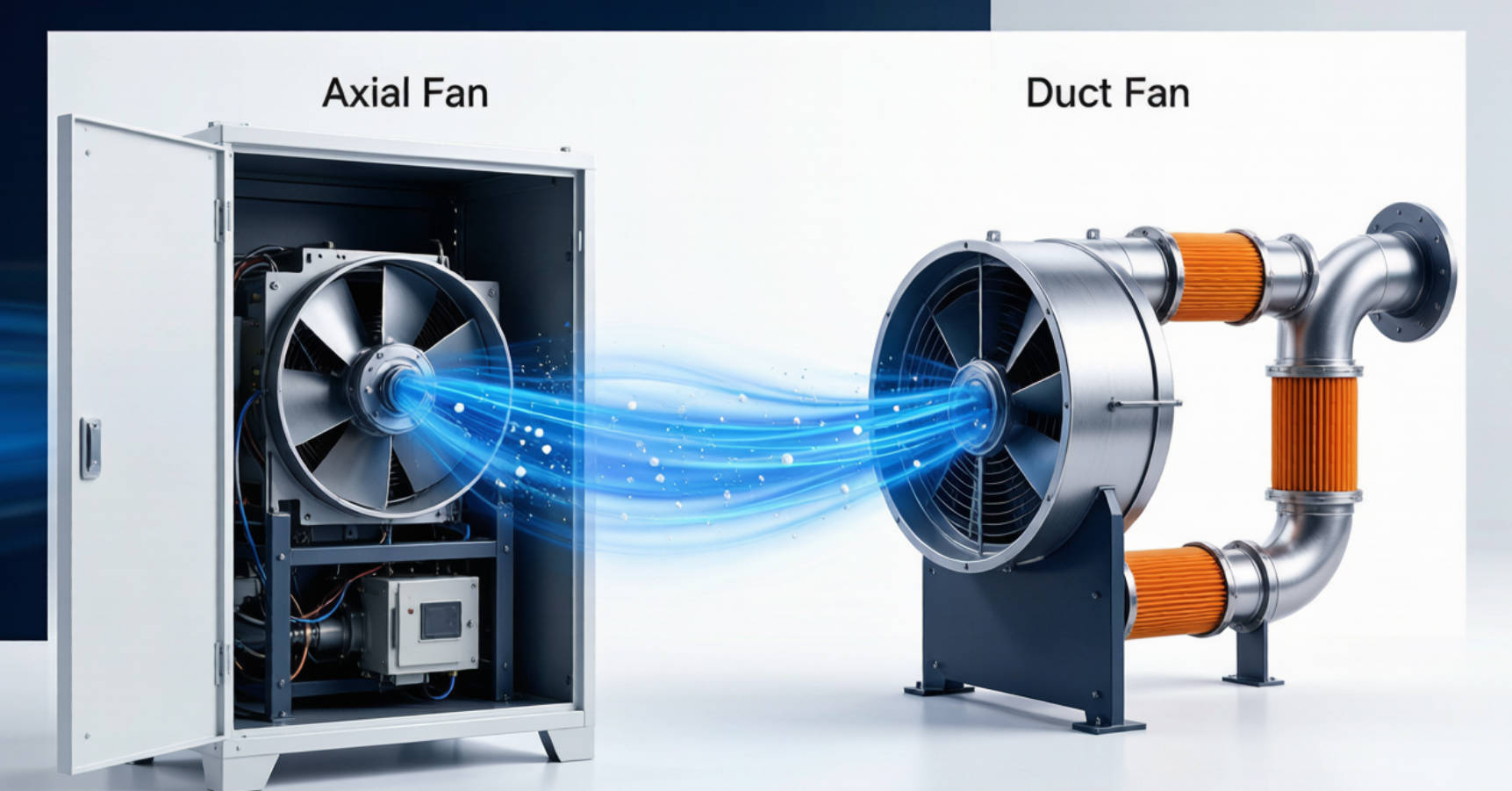
An axial fan moves air in the same direction as its rotating shaft. Its blades work similarly to a propeller: they create a pressure difference that pulls air in and pushes it forward.
For many electronics and industrial cooling applications, this design is highly effective because it can move a large volume of air through a relatively open path. DC axial fans are especially common in telecom cabinets, servers, power supplies, battery systems, automation equipment, and network hardware.
An axial fan is often the best choice when the system has minimal airflow resistance.
- High airflow capability in a compact footprint
- Simple structure and relatively easy installation
- Suitable for direct cooling of heat-generating components
- Available in AC and DC motor versions
- Can support intelligent speed control, tachometer output, alarms, and PWM control
- Well suited to open-air intake and exhaust applications
In equipment cooling, axial fans are frequently installed at an air inlet or outlet panel to establish front-to-back or bottom-to-top airflow. This approach works well when internal obstructions are controlled and the air path is short.

The main limitation is pressure capability. As duct length, filter loading, grille resistance, heatsink density, or airflow obstruction rises, actual airflow can decline sharply.
An axial fan may underperform when installed in:
- Long or narrow ducts
- High-density filters
- Systems with multiple elbows
- Air-cleaning or dust-collection equipment
- High-resistance heat exchanger assemblies
- Poorly designed cabinet airflow paths
This does not mean axial fans are unsuitable for ducts. A properly engineered tube axial or vane axial fan can be used in ducted systems. However, the pressure requirement must be verified against the manufacturer's fan curve rather than assumed from free-air CFM data.
A duct fan is installed inside or connected directly to ductwork to move air through a controlled ventilation path. Depending on the configuration, it may use axial, mixed-flow, or centrifugal impeller technology.
For practical selection, the term usually describes an inline fan designed to maintain airflow in systems with meaningful static pressure. These fans are commonly used in ventilation, industrial exhaust, air filtration, battery-room ventilation, machine enclosures, HVAC systems, workshops, and process equipment.
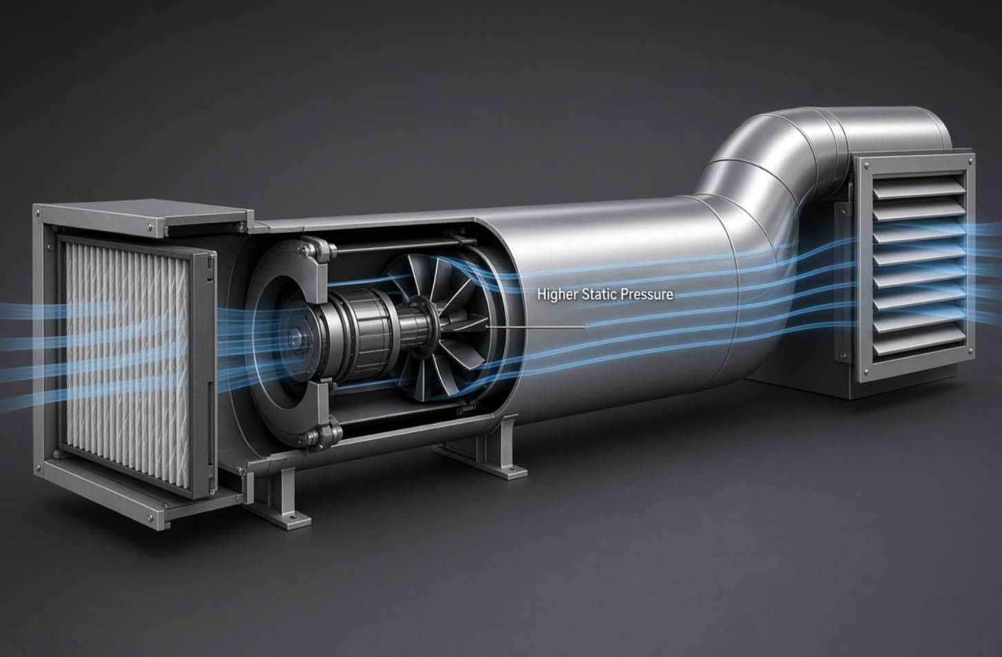
A duct fan is designed to keep air moving when the system introduces resistance.
- Higher static pressure capability than a typical free-air axial fan
- Better fit for long ducts, bends, dampers, filters, and grilles
- Enclosed airflow path improves safety and installation flexibility
- Can be installed remotely from occupied or noise-sensitive areas
- Suitable for supply air, exhaust air, filtration, and localized extraction
- Mixed-flow and centrifugal designs can provide stable airflow across a wider resistance range
A duct fan is particularly valuable when airflow must reach a specific point rather than simply circulate within an open room or cabinet.
Duct fans usually require more planning than open-mounted axial fans. Duct diameter, transition design, access for maintenance, vibration isolation, condensate risk, and electrical service should be considered before installation.
Potential trade-offs include:
- Higher initial system cost
- More installation work
- Possible noise if the fan is undersized and forced to run at maximum speed
- Performance loss from poor inlet or outlet duct geometry
- Ongoing filter and duct maintenance requirements
The most important distinction in the duct fan vs. axial fan decision is the relationship between airflow and static pressure.
Airflow is commonly expressed as:
- CFM: cubic feet per minute
- m³/h: cubic meters per hour
- L/s: liters per second
Static pressure represents the resistance the fan must overcome. It can come from duct friction, filters, bends, grilles, louvers, silencers, heat exchangers, dampers, and component obstructions.
A fan curve plots airflow against pressure. At free air, the fan may deliver its maximum airflow. As system resistance increases, airflow decreases. The real operating point is where the fan curve intersects the system curve.
| System Condition | Recommended Starting Point |
|---|---|
| Open equipment cabinet with short airflow path | DC or AC axial fan |
| Outdoor electrical enclosure with louver and filter | High-static-pressure axial fan or blower |
| Long duct route with bends and filter | Inline duct fan |
| Fume extraction or air cleaning | Duct fan, often centrifugal or mixed flow |
| Telecom cabinet with dense electronics | High-performance DC axial fan |
| Battery room exhaust through ductwork | Duct fan selected for pressure and safety requirements |
| Warehouse air circulation | Large axial fan or industrial axial ventilation fan |
AMCA notes that adverse flow conditions near a fan inlet or outlet can cause system effect—losses caused by turbulence or swirl that reduce real installed performance. It recommends considering duct transitions, nearby fittings, and accessories as part of the selection process.
A reliable selection process should begin with system requirements, not with a product catalog.
Start with the heat load, ventilation target, or extraction requirement.
For electronics cooling, airflow demand is linked to heat dissipation and allowable temperature rise. For ventilation, it depends on room volume, air-change requirements, contaminants, humidity, occupancy, and applicable local codes.
Do not specify only "high airflow." Define:
- Required airflow at the actual operating condition
- Ambient temperature range
- Air density or altitude, where relevant
- Allowed temperature rise
- Required service life
- Duty cycle: continuous, intermittent, or emergency operation
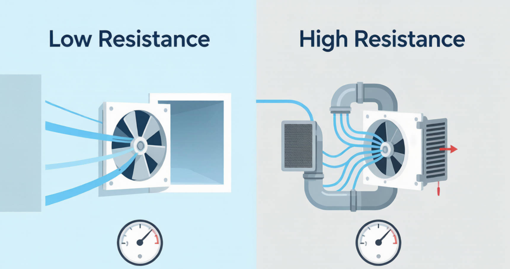
List every item that creates pressure loss:
- Duct length and diameter
- Elbows and transitions
- Filters and filter loading over time
- Protective finger guards
- Louvers and grilles
- Dampers and backdraft shutters
- Heat exchangers
- Sound attenuators
- Internal equipment obstructions
This step is essential. A fan selected without resistance data may meet its catalog airflow rating but fail to deliver sufficient air in the finished installation.
Select the fan based on the point where required airflow and total system pressure meet. Also review:
- Input power
- Current draw
- Sound level
- Efficiency
- Speed range
- Motor protection
- Bearing type
- IP rating
- Control signal compatibility
- Alarm or failure-detection functions
For critical systems, request full fan performance data rather than relying only on a single "maximum airflow" figure. AMCA testing standards evaluate airflow, pressure, input power, speed, air density, and efficiency for performance-rating purposes.
Noise is not only a comfort issue. It can indicate turbulent inlet conditions, excessive fan speed, poor mounting, structural vibration, or an unsuitable fan type.
To reduce noise:
- Use a larger fan operating at a lower speed where possible
- Avoid sharp restrictions at the inlet
- Add appropriate vibration isolation
- Avoid undersized ducts
- Use speed control to match real demand
- Consider duct attenuation for occupied spaces
- Verify sound data at the intended operating point
For equipment cooling, DC fans with PWM speed control can help balance cooling, power use, and acoustics. For building ventilation, EC motor duct fans can provide useful speed adjustment where airflow demand varies.
In our technical experience, poor installation can make a properly selected fan appear defective. The fan is often blamed, but the root cause is frequently the surrounding air path.
- Installing an elbow directly at the fan inlet
- Reducing duct diameter too close to the fan
- Using abrupt transitions instead of gradual ones
- Placing a dense filter without allowing for pressure increase as it loads
- Blocking the discharge with a grille or equipment wall
- Ignoring vibration transmission to panels or ductwork
- Selecting a fan only by maximum free-air airflow
- Failing to test airflow and temperature after installation
AMCA guidance indicates that outlet ducting needs sufficient length for airflow to develop. As a rule of thumb, it cites at least 2.5 duct diameters at velocities up to 2,500 fpm, with added length at higher velocities; it also recommends separation between an elbow and the fan to reduce system effects.
Consider a telecom power cabinet with a 2 kW heat load. The cabinet has front louvers, washable filters, cable congestion, a dense power-conversion section, and rear exhaust openings.
A standard axial fan may show a strong free-air rating. However, once the filter and internal restrictions are added, the actual operating point may move to a much lower airflow level. In this scenario, the better solution may be a high-static-pressure DC axial fan, a fan tray using multiple controlled fans, or a redesigned airflow path.
Now consider an industrial battery room where warm air must travel through 15 meters of ductwork, multiple elbows, an external weather louver, and a backdraft damper. A duct fan selected for the calculated static pressure is more appropriate. An open-mounted axial fan is unlikely to maintain the required airflow reliably as resistance changes.
For mission-critical telecom, server, and industrial equipment, reliability should be evaluated alongside airflow. SANYO DENKI specifies certain long-life DC fan models with expected life up to 180,000 hours under stated L10 conditions: rated voltage, continuous operation, free air, and 60°C ambient temperature.
A fan is a system component, not a standalone commodity. Two fans with similar dimensions and nominal airflow can perform very differently once pressure, temperature, control requirements, acoustics, and reliability targets are considered.
Capital Technology can support project-specific selection for DC fans, AC fans, high-static-pressure cooling fans, and industrial ventilation solutions. Our approach is to review the actual application conditions before recommending a model or configuration.
Provide the following information for a faster recommendation:
1. Required airflow and expected static pressure
2. Fan dimensions and mounting method
3. Voltage, frequency, and control requirements
4. Ambient temperature and humidity
5. Continuous operating hours and target service life
6. Noise limit and installation environment
7. Duct drawing, cabinet layout, or equipment photos
8. Any filter, grille, heatsink, or airflow obstruction details
Need a reliable cooling or ventilation solution? Contact Capital Technology with your airflow requirement, voltage, dimensions, and application drawing. Our engineering team can help you compare duct fan and axial fan options, review the operating point, and recommend a suitable CAPITAL or SANYO DENKI solution.
An axial fan moves a high volume of air efficiently when resistance is low. A duct fan is better suited to systems with duct runs, filters, bends, dampers, and other sources of static pressure.
Yes. Tube axial and vane axial fans can be installed in ducts. However, the fan must be selected from its performance curve at the expected system pressure. A general-purpose axial fan may not provide enough airflow in a high-resistance duct system.
No. Noise depends on fan speed, blade design, airflow turbulence, mounting, duct geometry, and the surrounding environment. A properly selected axial fan in an open path may be very quiet, while an undersized duct fan running at high speed can be loud.
Filters add static pressure, and their resistance normally increases as they collect dust. Select the fan using both clean-filter and final loaded-filter pressure conditions to avoid airflow loss over the maintenance cycle.
High-static-pressure DC axial fans are often suitable for telecom cabinets because they provide compact, controllable cooling through moderately restrictive airflow paths. The final choice depends on cabinet layout, heat load, filter design, and redundancy requirements.
Use the correct fan type, avoid unnecessary system resistance, select efficient motors, use variable-speed control, maintain clean filters, and operate the fan near its efficient duty point rather than continuously at maximum speed.
1. [AMCA Publication 201-23: Fans and Systems]-fans-and-systems.html) — Fan-system interaction, laboratory ratings, and system effect factors. [amca]-fans-and-systems.html)
2. [AMCA: Mitigating System Effect to Optimize Fan Performance and Efficiency] — Causes of system effect and duct-layout recommendations. [amca]
3. [ANSI/AMCA Standard 210-25: Laboratory Methods of Testing Fans] — Standardized methods for evaluating fan airflow, pressure, power, speed, air density, and efficiency. [amca]
4. [AMCA Standard 210-16 Educational Material] — Definitions of fan air power, total efficiency, and static efficiency. [amca]
5. [Capital Technology Co., Limited: About Us] — Company background, CAPITAL brand capability, SANYO DENKI chief-agent status, and listed customer relationships. [sanyodenki-cn]
6. [SANYO DENKI Long Life Fan Product Information] — Long-life fan specifications and stated L10 operating conditions. [products.sanyodenki]
7. [SANYO DENKI Long Life Fan PDF] — Expected service-life definition and 180,000-hour maximum claim under specified test conditions. [sanyodenki]


