From idea to market-ready product, our NPI solutions make every stage easier, faster. Discover How We Help
Help Center

Views: 211 Author: Capital Technology Publish Time: 2026-10-20 Origin: Site
Content Menu
● Where Are Industrial Cooling Fans Used?
>> Telecommunications and Network Equipment
>> Industrial Automation and Power Electronics
>> Retail Equipment and Refrigerated Displays
● DC Fan vs. AC Fan: Which Technology Fits Your Equipment?
>> When a DC Cooling Fan Makes Sense
>> When to Consider an AC or ACDC Fan
● Airflow and Static Pressure: Read the Performance Curve
>> Why Maximum Airflow Can Be Misleading
>> Check the Entire Airflow Path
● How to Estimate Required Cooling Airflow
>> Worked Example: A 300 W Enclosure
● A Six-Step Cooling Fan Validation Process
>> 1. Define the Thermal Limits
>> 2. Confirm Mechanical and Electrical Compatibility
>> 3. Compare Installed Performance
>> 4. Test the Complete Assembly
>> 5. Evaluate Degraded Conditions
>> 6. Document the Approved Configuration
● Balancing Noise, Energy Consumption, and Cooling
● Reliability: Interpret Fan Life Ratings Carefully
● What Buyers Should Include in a Cooling Fan Inquiry
>> 1. What is the main difference between a DC fan and an AC fan?
>> 2. Is a higher-CFM cooling fan always better?
>> 3. Can an AC fan be replaced with a DC fan?
>> 4. How do I select a fan for a dusty cabinet?
>> 5. Does PWM control automatically reduce noise?
>> 6. How can I confirm that a selected fan is sufficient?
Choosing the right DC fan or AC fan starts with understanding what the equipment needs—not simply matching a frame size or selecting the highest airflow rating. In industrial cooling, reliable performance depends on heat generation, airflow resistance, power availability, and operating conditions.
Cooling fans work behind the scenes in telecommunications equipment, automation systems, retail electronics, and refrigeration. Some remove heat from electronic components. Others circulate air, support drying, or assist material handling.
For equipment designers and purchasing teams, the practical question is straightforward: how do you select a cooling fan that performs reliably inside the finished product?
This guide explains where industrial fans are used, how different fan technologies compare, and how to turn a cooling requirement into a testable specification.
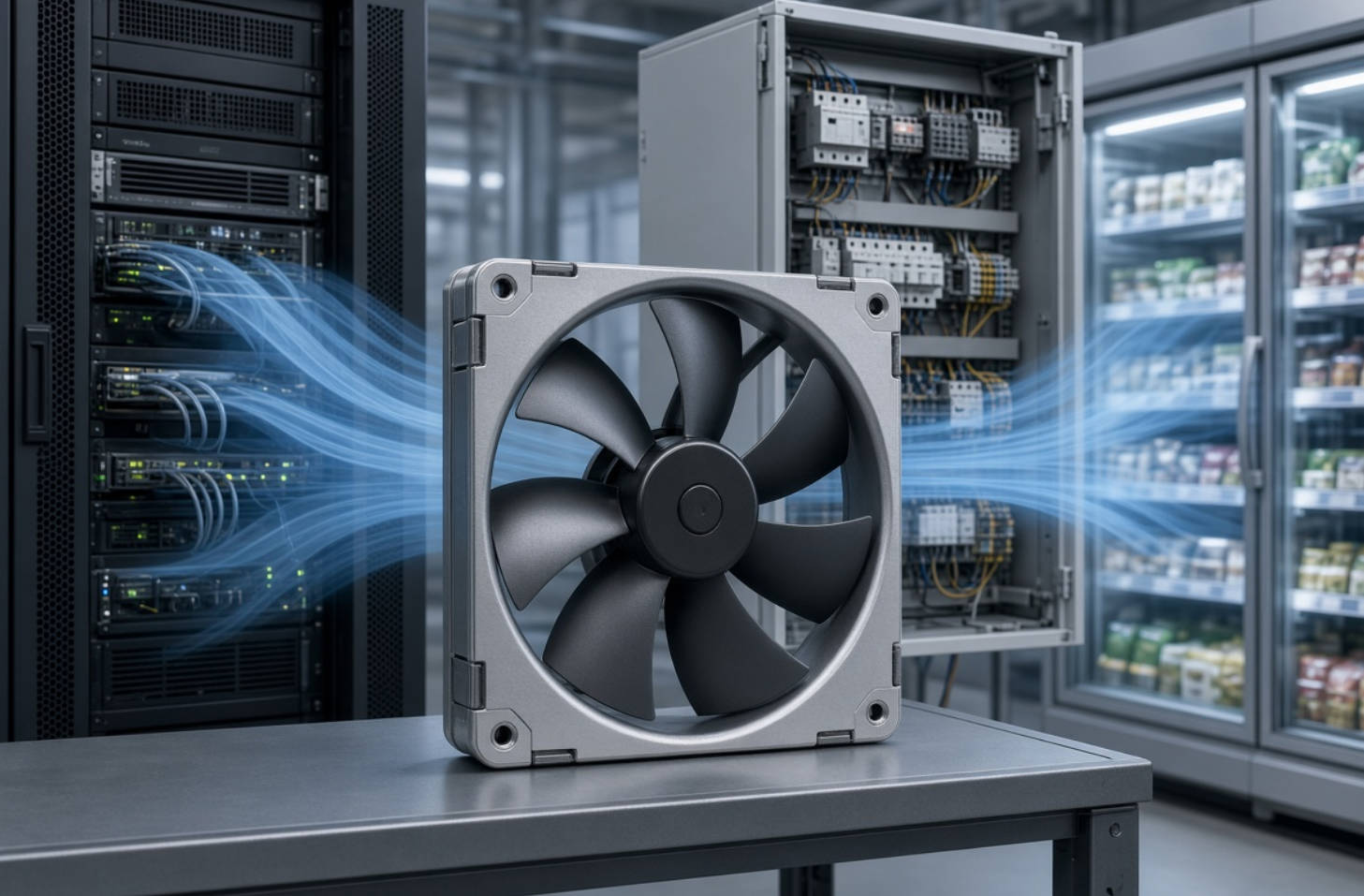
A fan's purpose depends on the equipment around it. Understanding that purpose helps prevent a common mistake: treating every application as a simple ventilation problem.
Network switches, communication cabinets, and related electronics use forced airflow to carry heat away from internal components.
These installations may contain densely arranged boards, heat sinks, protective grilles, and filters. Each obstruction affects airflow.
The selection priority is therefore not just air volume. It is maintaining sufficient airflow against the resistance of the complete enclosure.
Designers must also consider service access, fan monitoring, and what happens if cooling performance deteriorates.
Control cabinets, drives, and power-conversion equipment generate heat during operation. Fans help transfer that heat into an exhaust stream or through a heat exchanger.
A practical assessment should consider:
- Maximum equipment load.
- Local temperature around the fan.
- Dust exposure and filter condition.
- Available inlet and outlet space.
- Maintenance intervals.
A fan that works on an open test bench may behave differently after installation behind a restrictive cabinet grille.
SANYO DENKI identifies ATMs, point-of-sale systems, surveillance cameras, copiers, and refrigerated displays as fan applications.
Their requirements differ. An ATM may need cooling for control electronics, while a refrigerated display uses circulation to reduce temperature variation.
In printing equipment, airflow can also assist paper separation and ink drying.
The lesson is important: define the required airflow function before choosing the fan.
Power architecture provides a useful starting point, but it should not determine the entire selection.
| Selection factor | DC fan | Conventional AC fan | ACDC or EC fan |
|---|---|---|---|
| Power input | Requires a compatible DC supply | Uses a specified AC supply | Accepts AC and converts it internally |
| Speed adjustment | Available on appropriately equipped models | Depends on motor design and approved controls | Available on appropriately equipped models |
| Typical selection context | Equipment with an existing DC power rail | Equipment designed around AC-powered ventilation | AC-powered equipment seeking electronically controlled operation |
| Important checks | Voltage range, current, control signals | Voltage, frequency, control compatibility | Input range, control interface, electrical requirements |
| Main caution | Control features vary by model | Performance can depend on supply conditions | Do not assume every model has identical functions |
A DC cooling fan is worth considering when the equipment already provides a suitable DC supply.
Models with PWM control allow speed adjustment through a control signal. This can help align cooling output with changing thermal demand.
However, voltage alone does not establish compatibility. Check startup current, connector pinout, signal levels, and permitted operating conditions.
A physically interchangeable fan may still be electrically incompatible.
A conventional AC fan can suit equipment with an appropriate AC supply and a straightforward ventilation requirement.
An ACDC fan, also called an EC fan in SANYO DENKI's product terminology, incorporates AC-to-DC conversion. Certain models combine AC input with PWM speed control.
These categories should not be ranked with blanket claims. Compare specific models at the required operating point, including power consumption, noise, life conditions, and installation constraints.
The most important selection principle is this: airflow ratings must be interpreted in the context of system resistance.
Maximum airflow describes performance near the free-air end of a fan's characteristic curve. Maximum static pressure describes the opposite endpoint, where airflow approaches zero.
These maximum values do not occur simultaneously.
Filters, heat sinks, cables, circuit boards, and ventilation openings restrict air movement. Together, they create system impedance.
Actual operating airflow occurs where the fan's pressure–airflow curve intersects the system-resistance curve.
Consequently, two fans with similar maximum airflow ratings can deliver different airflow inside the same enclosure.
For a densely packed cabinet, compare pressure–airflow curves rather than relying on a single CFM figure.
Also assess whether the proposed operating region is suitable for stable operation.
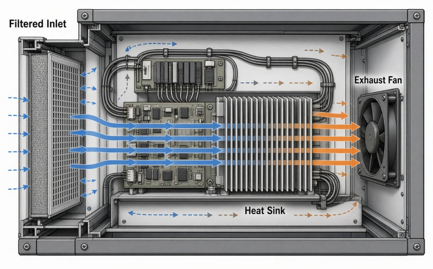
A useful engineering review follows air from inlet to outlet:
1. Identify where cooler air enters.
2. Check whether it reaches critical components.
3. Look for gaps that allow bypass airflow.
4. Identify narrow passages and restrictive accessories.
5. Check whether exhaust can return to the inlet.
Increasing fan speed cannot reliably compensate for an airflow path that avoids the components needing cooling.
A heat-balance calculation provides a starting point for ventilation sizing. It does not replace an installed thermal test.
For a simplified steady-state estimate:
Q=P/ρcpΔT
Where:
- Q is volumetric airflow in cubic metres per second.
- P is the heat transferred to the air, in watts.
- ρ is air density.
- cp is the specific heat capacity of air.
- ΔT is the permitted bulk-air temperature rise.
Consider an illustrative enclosure transferring 300 W into its ventilation air, with a permitted air-temperature rise of 10°C.
Using approximate room-condition values of 1.2 kg/m3 for air density and 1,005 J/(kg⋅K) for specific heat gives:
Q≈0.0249 m3/s
That is approximately 90 m³/h, or 53 CFM.
This result is an idealized bulk-air requirement—not a recommendation to purchase a fan rated at 53 CFM maximum airflow.
The selected fan must deliver the required flow against enclosure resistance. Component hot spots, bypass leakage, altitude, and other heat-transfer paths also affect the final design.
Most importantly, bulk exhaust temperature does not establish the temperature of every component.
A disciplined validation process turns a promising catalog selection into a defensible equipment decision.
Record maximum ambient temperature, operating load, allowable component temperatures, and permitted internal air-temperature rise.
Identify which limits come from component specifications and which are project targets.
Check frame dimensions, thickness, mounting holes, airflow direction, cable routing, voltage, current, and connector details.
For controlled fans, confirm PWM and speed-feedback requirements from the exact model documentation.
Use pressure–airflow curves and an estimated or measured system-resistance curve to shortlist candidates.
Where system resistance is uncertain, use prototype testing to establish whether the chosen fan delivers adequate cooling.
Install the intended grilles, filters, panels, cables, and internal components.
Measure critical temperatures under representative operating loads. Open-cover testing is not a substitute for testing the finished airflow path.
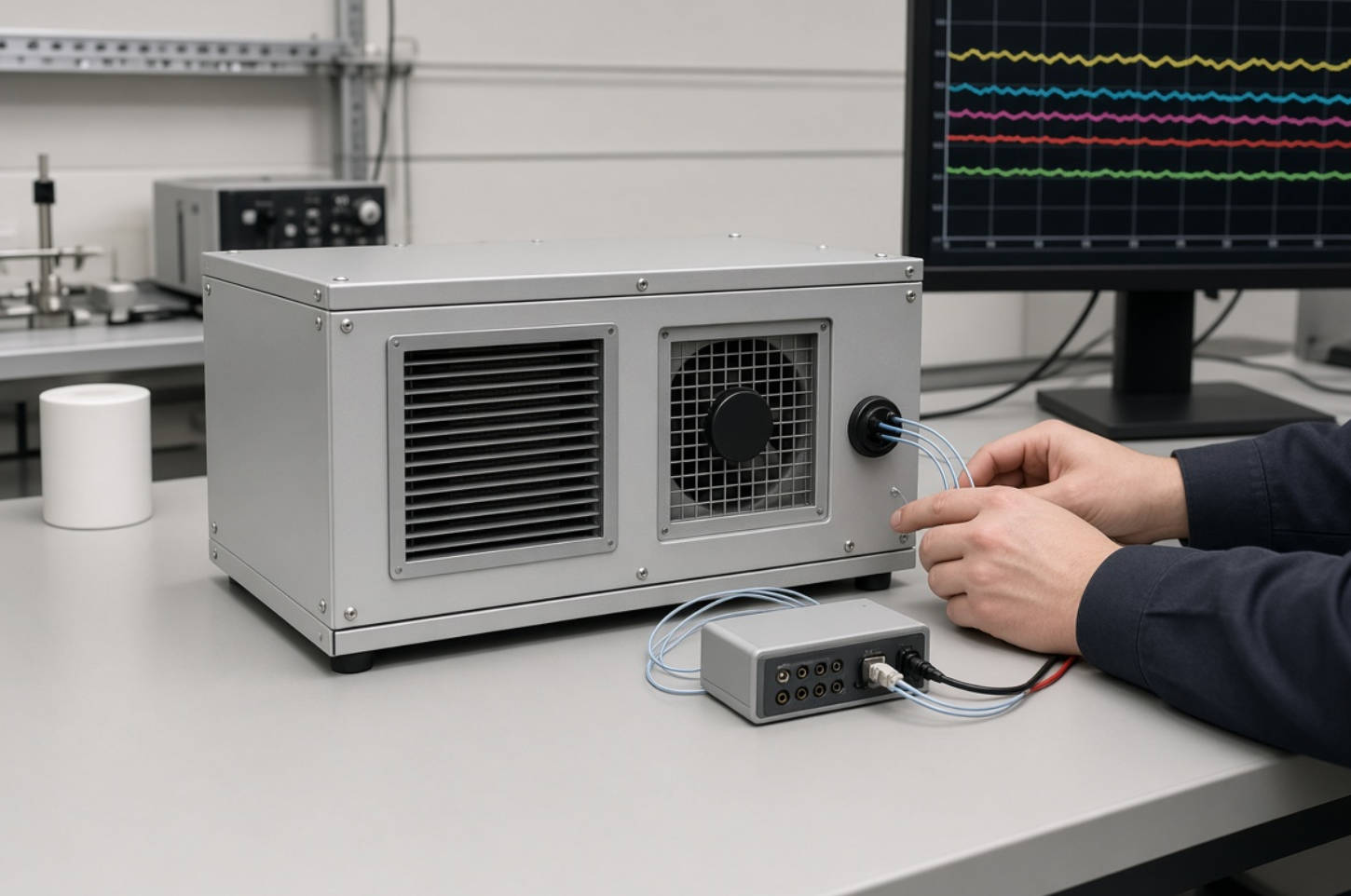
Where relevant, assess warmer inlet air, partial filter loading, restricted openings, and fan-failure scenarios.
Define acceptable behavior before testing: continued operation, reduced output, an alarm, or controlled shutdown.
Record the exact fan model, test conditions, control settings, temperature results, and acceptance criteria.
This makes later substitutions easier to evaluate and helps prevent purchasing changes from invalidating the thermal design.
Running a fan at full speed continuously may provide unnecessary cooling during light-load operation.
Where supported, PWM control allows fan speed to follow equipment demand. However, the control strategy needs validation, not just a temperature setpoint.
For geometrically unchanged fans under comparable conditions, fan laws indicate approximately:
- Airflow varies with rotational speed.
- Pressure varies with speed squared.
- Aerodynamic power varies with speed cubed.
These relationships explain why speed reduction can be valuable. They do not guarantee identical reductions in measured electrical input, because motor and electronic losses also matter.
A practical control strategy should include minimum reliable speed, startup behavior, sensor-failure response, and protection against rapid speed cycling.
Noise should also be evaluated after installation. Mounting, obstructions, and structural vibration can change the sound experienced by users.
An expected-life figure is meaningful only when its conditions are understood.
For example, SANYO DENKI specifies certain products using L10 life: the stated operating period associated with a 90% survival rate under defined conditions.
That is not a promise that every fan will operate for exactly that duration.
Before comparing two life ratings, check:
- Ambient temperature.
- Applied voltage.
- Test conditions and installation assumptions.
- Applicable failure criteria.
- Whether the figure is specified or provided for reference.
Environmental suitability requires similar care. Dust, moisture, temperature extremes, and chemical exposure need model-specific assessment.
Do not assume that an environmentally protected fan makes the complete enclosure equally protected.
A detailed inquiry helps suppliers recommend suitable products and reduces avoidable sampling cycles.
| Information to provide | Why it matters |
|---|---|
| Equipment type and application | Establishes operating context |
| Heat load and temperature limits | Defines the thermal requirement |
| Available fan dimensions | Establishes mechanical constraints |
| Supply voltage and frequency | Confirms electrical compatibility |
| Target operating airflow and pressure | Supports meaningful performance matching |
| Filters, grilles, and enclosure drawings | Helps assess resistance |
| Noise and control requirements | Guides speed-control selection |
| Environment and service expectations | Supports reliability assessment |
| Quantity, schedule, and documentation needs | Clarifies procurement requirements |
Capital Technology Co., Limited provides DC fan, AC fan, and cooling-solution options through its CAPITAL brand and SANYO DENKI agency business. Its supplied company information identifies ZTE, HUAWEI, and HYTERA among its customers.
For a project-specific recommendation, send Capital your enclosure dimensions, heat load, power supply, operating environment, and target quantity. Request candidate datasheets and performance curves, then validate the selected configuration in your equipment before production approval.
The main distinction is the required electrical supply and associated motor design. Select by the exact model's voltage, performance, control features, and operating requirements—not the power category alone.
No. Maximum CFM is not installed airflow. A restrictive enclosure may require a fan with stronger pressure capability at the required flow rather than a higher free-air rating.
Potentially, but this is an electrical and thermal redesign decision. Check the DC supply, mounting, wiring, controls, protection requirements, and installed cooling performance before approving a replacement.
Assess the filtration arrangement, expected filter loading, maintenance interval, and fan environmental specifications. Confirm that adequate airflow remains available under the relevant filter condition.
Not automatically. It enables speed adjustment on compatible fans, but the result depends on the operating speed, airflow path, mounting, and control behavior. Test noise in the finished assembly.
Test the complete equipment at defined ambient temperatures and operating loads. Monitor critical component temperatures and verify that all acceptance limits remain satisfied, including relevant degraded conditions.
1. [SANYO DENKI — "Where Are Fans Used?"]
Original article, supervised by the Cooling System Design Department. Supports the application examples involving retail electronics, printing, and refrigerated displays. [techcompass.sanyodenki]
2. [SANYO DENKI — "Basic Knowledge for Selecting a Cooling Fan"]
Supports selection considerations covering size, electrical compatibility, system resistance, environment, noise, and control. [techcompass.sanyodenki]
3. [SANYO DENKI — "Fan Airflow and Static Pressure"]
Supports the explanation of airflow, static pressure, characteristic curves, and installed operating points. [techcompass.sanyodenki]
4. [SANYO DENKI — "Guideline in Selecting a Fan"]
Supports heat-load-based airflow estimation and the need for final selection through actual installation testing. The 300 W example is an independently calculated illustration, not a reported customer case. [products.sanyodenki]
5. [SANYO DENKI — "Features of ACDC Fans (EC Fans)"]
Supports the description of internal AC-to-DC conversion and model-dependent PWM functionality. [techcompass.sanyodenki]
6. [AMCA International — "Derivation of the Fan Laws"]
Technical basis for relationships between rotational speed, airflow, pressure, density, and aerodynamic power. [amca]
7. [SANYO DENKI — DC Fan Technical Catalog]
Supports catalog definitions of maximum airflow, maximum static pressure, operating temperature, and expected-life conditions. [sanyodenki]


