From idea to market-ready product, our NPI solutions make every stage easier, faster. Discover How We Help
Help Center

Views: 215 Author: Capital Technology Publish Time: 2026-10-12 Origin: Site
Content Menu
● Counter Rotating Fan vs High Static Pressure DC Fan: Understanding the Difference
>> What Is a Counter Rotating Fan?
>> What Is a High Static Pressure DC Fan?
● Technical Comparison: Performance, Space, Noise, and Cost
>> Static Pressure: Compare Curves, Not Just Maximum Values
>> Installation Depth: Check the Entire Assembly
>> Noise and Energy: Compare at Equal Cooling Duty
● Published Product Data: What Higher Pressure Actually Means
● Which Fan Should You Choose for Your Application?
>> Counter Rotating Fans for High-Density Server Cooling
>> High Static Pressure DC Fans for Telecom and Industrial Equipment
>> Filtered Enclosures: Design for the Maintenance Condition
● A Practical Five-Step Fan Selection Process
>> 1. Define the Thermal and Mechanical Requirements
>> 2. Establish System Resistance
>> 3. Compare Candidate Performance Curves
>> 4. Validate Controls and Fault Behavior
>> 5. Test the Installed Equipment
● Three Expert Insights That Improve the Decision
>> Pressure Reserve Is More Useful Than an Arbitrary Percentage Margin
>> Two Stages Do Not Automatically Mean Redundancy
>> Improving the Air Path Can Be Better Than Increasing Fan Power
● Working With Capital Technology Co., Limited
● Conclusion: Choose the Fan That Meets the Installed Requirement
>> 1. Is a Counter Rotating Fan Also a High Static Pressure DC Fan?
>> 2. Does a Counter Rotating Fan Reverse the Airflow?
>> 3. Can Two Ordinary DC Fans Replace a Counter Rotating Fan?
>> 5. Which Fan Is Better for a Dense Heatsink?
>> 6. What Information Should I Send a Fan Supplier?
Choosing between a counter rotating fan and a high static pressure DC fan starts with understanding your equipment's airflow resistance. A counter rotating fan is worth considering when dense components and restrictive airflow paths demand substantial pressure. A single-stage high static pressure DC fan is often the more practical starting point when installation depth is limited and its performance curve meets the cooling requirement.
However, these categories overlap. Counter rotating fans are also DC fans capable of high static pressure. The meaningful comparison is between a two-stage counter-rotating design and a conventional single-stage pressure-optimized axial fan.
From a thermal-solution supplier's perspective, the deciding factor is the operating point: the airflow and pressure a fan actually delivers inside your equipment.
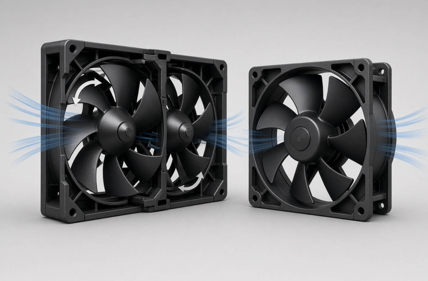
A counter rotating fan incorporates two impellers arranged along the same airflow path. The front and rear impellers rotate in opposite directions, while both stages move air through the assembly in the same overall direction.
The rear stage reduces the swirling airflow produced by the front stage. When the impellers, motors, and housing are designed together, this arrangement supports high airflow and static pressure in a compact frontal area.
It is not equivalent to placing two ordinary fans behind each other. Stage matching matters, including blade geometry, rotational speed, and the airflow entering the rear impeller.
Counter rotating cooling fans are particularly relevant to:
- High-density servers and network equipment.
- Restrictive heatsinks and closely packed components.
- Narrow airflow passages requiring substantial pressure.
- Equipment needing concentrated airflow toward heat sources.
"High static pressure" describes a performance characteristic, not one exclusive fan architecture.
For this comparison, a high static pressure DC fan means a single-stage axial fan engineered to move air through restrictive equipment. Its performance depends on the complete design: impeller geometry, frame, motor, rotational speed, and drive electronics.
This design can be suitable for power supplies, telecommunications equipment, industrial electronics, and servers where one impeller provides sufficient pressure.
Neither architecture is universally better. A well-selected single-stage fan can be preferable to an oversized counter rotating assembly.
| Selection factor | Counter rotating fan | Single-stage high static pressure DC fan |
|---|---|---|
| Architecture | Two oppositely rotating impellers | One pressure-optimized impeller |
| Main advantage | Strong pressure capability within a limited frontal area | Pressure capability with a simpler, potentially shallower assembly |
| Installation depth | Usually greater for a comparable frame size | Often easier to accommodate in shallow equipment |
| Airflow under resistance | Attractive for highly restrictive airflow paths | Effective when its pressure–airflow curve meets system demand |
| Noise | Depends on speed, stage interaction, and installation | Depends on speed, blade design, and installation |
| Power consumption | Must be checked at the required operating condition | Must be checked at the same operating condition |
| Integration | Requires attention to both stages and monitoring provisions | Generally fewer rotating components to integrate |
| Procurement | Potentially higher assembly complexity; obtain quotations | Potentially simpler sourcing; obtain quotations |
| Selection basis | Installed airflow and thermal validation | Installed airflow and thermal validation |
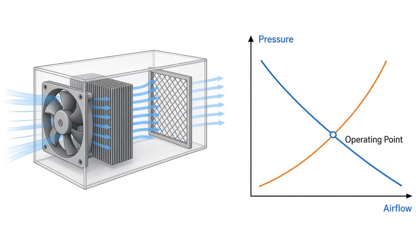
Maximum static pressure is measured at zero airflow. Maximum airflow is measured at approximately zero static pressure.
These figures describe opposite ends of a fan's pressure–airflow curve. They do not occur simultaneously.
Inside equipment, the fan operates where its performance curve intersects the system's resistance curve. This explains why a fan with impressive free-air airflow may deliver disappointing cooling through a dense heatsink.
Request the full pressure–airflow curve, often called the P–Q curve. Compare candidate fans at the pressure your equipment actually requires.
Two-stage fans often require more axial depth than single-stage alternatives with the same frame width.
However, the fan body is only part of the space requirement. Include:
- Connector and cable clearance.
- Fan guards and mounting hardware.
- Inlet and outlet clearance.
- Service access and removal space.
- Duct transitions and nearby obstructions.
A mechanically compatible fan can still perform poorly if its inlet is obstructed or discharged air immediately recirculates.
It is misleading to compare two fans only at their maximum speed.
Instead, adjust each candidate to deliver the required installed airflow, then compare electrical input and acoustic performance. A high-capability fan may run below maximum speed, but that does not automatically make it quieter or more efficient.
PWM speed control can help match cooling output to changing thermal demand. Confirm the model's control specifications rather than assuming identical behavior across products.
Published manufacturer data provides useful context, but it should not be treated as a universal comparison between architectures.
| Published example | Dimensions | Maximum airflow | Maximum static pressure |
|---|---|---|---|
| San Ace 80 9HVA high static pressure fan, described in a 2017 technical report | 80 × 80 × 38 mm | 3.75 m³/min | 1,350 Pa |
| San Ace 80 9CRHA counter rotating fan, released in May 2025 | 80 × 80 × 80 mm | 5.65 m³/min | 2,700 Pa |
These examples illustrate a tradeoff: the deeper counter rotating assembly offers greater published pressure capability. They are not a controlled head-to-head test. They differ in design generation, depth, and other specifications.
For the 12 V 9CRHA0812P8J001 model, the manufacturer also lists 144 W rated input and an 85 dB(A) sound pressure level. This makes clear that extreme pressure capability can come with significant electrical and acoustic requirements.
The 2025 release reports approximately 38% greater maximum static pressure than the preceding 9CRH counter rotating product. That improvement is a comparison between two counter rotating designs—not proof that every two-stage fan outperforms every single-stage fan.
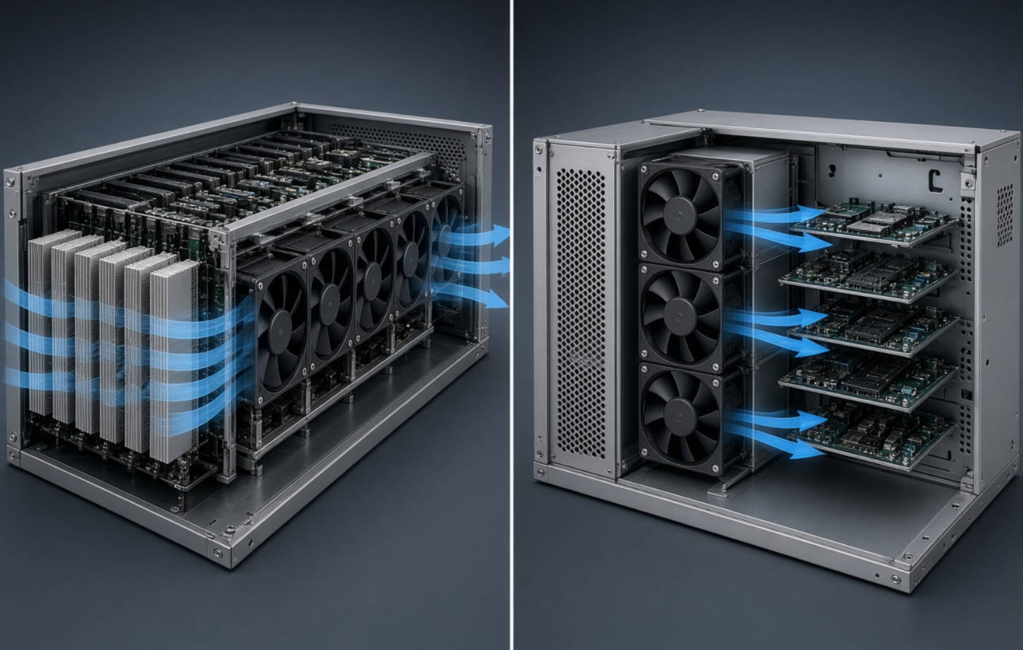
Consider a counter rotating fan when your server has a restricted frontal area, substantial airflow resistance, and enough installation depth.
Dense heatsinks and tightly packed components can require pressure capability that ordinary airflow-focused fans cannot provide at the required flow rate.
However, fan replacement should not be the only response to overheating. Check for bypass paths, blocked inlets, and recirculation before specifying a more powerful assembly.
A single-stage high static pressure DC fan is a sensible starting point when space is constrained and the thermal requirement is achievable with one stage.
Potential applications include network devices, power supplies, and industrial control equipment.
For equipment near people, acoustic limits may be as important as maximum cooling capacity. For outdoor installations, environmental suitability must be evaluated separately; high pressure capability does not imply water or dust protection.
Filters introduce airflow resistance, and their condition changes during service.
Compare candidate fans using the specified end-of-service filter resistance, not only a clean-filter condition. Then confirm that the equipment remains within its temperature limits.
Also review filter area and airflow-path geometry. Reducing unnecessary resistance may allow a lower-speed fan to meet the same cooling requirement.
Prepare a selection brief containing:
- Heat dissipation and critical component temperature limits.
- Maximum inlet-air temperature.
- Available frame size and installation depth.
- Supply voltage and electrical limits.
- Acoustic requirements.
- Environmental and service-life requirements.
Treat these as selection inputs, not details to resolve after choosing a model.
Measure the enclosure's resistance where practical. Manufacturer guidance describes using airflow-testing equipment to establish system impedance and operating airflow.
When measurements are unavailable, use preliminary estimates to shortlist candidates, then validate the assembled equipment.
Do not turn a rule-of-thumb airflow allowance into a final qualification criterion.
Locate each fan's intersection with the system resistance curve.
Check whether the resulting airflow meets the thermal requirement. Also review whether the intended operating region is stable.
A fan with a higher maximum pressure can still be unsuitable if its curve does not provide the required airflow at your system resistance.
Confirm PWM input requirements, speed-feedback signals, connectors, and supply compatibility.
For counter rotating fans, clarify how each stage is driven and monitored. Two impellers do not automatically provide fault-tolerant cooling.
Ask what happens if one stage stops, and validate any required fault response at equipment level.
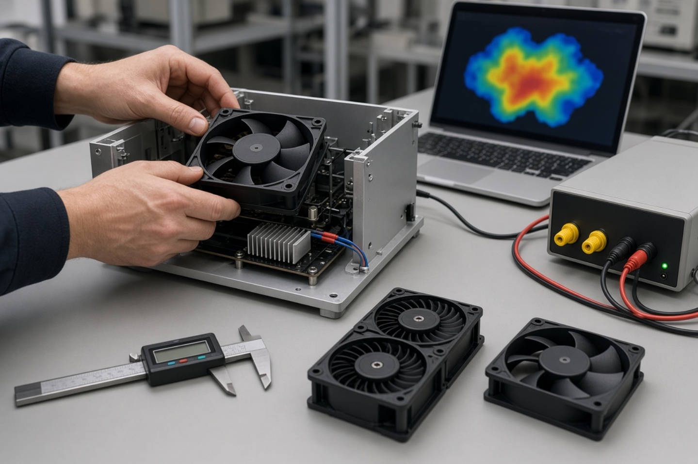
Test representative assemblies under the specified operating conditions.
Record component temperatures, installed airflow where measurable, electrical input, and noise. Include relevant filter conditions and fan-fault scenarios.
Select the candidate that satisfies the complete requirement—not simply the one with the highest catalog rating.
There is no single pressure-margin percentage suitable for every enclosure.
Identify what may increase resistance: filter loading, manufacturing variation, airflow-path changes, or future component additions. Evaluate those conditions against the candidate curves.
This produces a defensible margin tied to the equipment, rather than a generic safety factor.
A counter rotating fan is an integrated aerodynamic assembly.
If one stage stops, the remaining stage operates under changed conditions. The stopped impeller can also affect the airflow path.
Where continuous operation after failure is required, specify and test that requirement explicitly. Do not infer redundancy from the number of motors.
Before escalating fan capability, inspect restrictive guards, undersized openings, poorly routed cables, and abrupt duct transitions.
Addressing these issues may improve installed airflow without increasing maximum fan speed.
This is particularly valuable when a project must balance cooling, noise, electrical capacity, and serviceability.
Capital Technology Co., Limited focuses on DC fans and thermal-management solutions through its CAPITAL brand and SANYO DENKI product offering.
As a manufacturer and SANYO DENKI chief agent, the company can frame selection around both equipment requirements and product sourcing. Its supplied company background identifies ZTE, HUAWEI, and HYTERA among its customers; those relationships should not be interpreted as validation of a particular fan configuration.
For a useful technical inquiry, provide your enclosure dimensions, heat load, voltage, temperature limits, noise target, and available airflow-resistance data.
Request a comparison of suitable CAPITAL and SANYO DENKI candidates, supported by model-specific curves and a clear sample-validation plan.
Choose a counter rotating fan when substantial airflow resistance and limited frontal area justify a two-stage assembly, and your equipment can accommodate its depth, electrical demand, and acoustic behavior.
Choose a single-stage high static pressure DC fan when it meets the required operating condition with a more suitable mechanical and commercial fit.
Send Capital Technology Co., Limited your thermal and mechanical requirements to request a model shortlist, performance-curve comparison, and sample-selection discussion before committing to production.
Yes. Many counter rotating fans are DC-powered fans designed for high static pressure. "Counter rotating" describes the architecture, while "high static pressure" describes performance. This article compares two-stage counter rotating fans with single-stage pressure-optimized axial fans.
No. Its impellers rotate in opposite directions, but both stages support airflow in the same overall direction. It should not be confused with a reversible-flow fan designed to change airflow direction.
Do not assume equivalent performance. An integrated counter rotating fan uses matched stages to manage the airflow between impellers. Two ordinary fans installed in series require their own performance and equipment-level validation.
Neither architecture is inherently quieter in every application. Compare model-specific acoustic data under comparable test conditions, then evaluate both candidates in the enclosure at the required cooling duty.
A counter rotating fan is worth considering when resistance is especially high. However, a single-stage high static pressure fan may still provide sufficient airflow. Compare performance curves and confirm critical component temperatures through testing.
Provide heat load, inlet temperature, allowable component temperatures, installation dimensions, voltage, noise limits, and environmental requirements. Include system-resistance measurements or existing fan data where available, plus any monitoring and failure-response requirements.
1. [SANYO DENKI, "Features of Counter Rotating Fan," Tech Compass]. Supervised by the Cooling System Design Department. Supports the explanation of opposite impeller rotation, reduced swirl, matched-stage design, and high-resistance applications. [techcompass.sanyodenki]
2. [SANYO DENKI, "Basic Knowledge for Selecting a Cooling Fan," Tech Compass]. Supports the discussion of airflow, static pressure, ventilation resistance, and PWM speed control. [techcompass.sanyodenki]
3. [SANYO DENKI, "SANYO DENKI Develops 80 × 80 × 80 mm Counter Rotating Fan with the Highest Static Pressure in the Industry," May 2025]. Source for the 9CRHA specifications, release timing, electrical input, sound pressure level, and comparison with the preceding 9CRH product. The manufacturer’s industry-ranking claim is time-limited and is not adopted as a current ranking in this article. [sanyodenki]
4. [SANYO DENKI, "Cooling Systems Division," Technical Report No. 43, May 2017]. Source for the 80 × 80 × 38 mm 9HVA example, its published airflow and pressure, and discussion of airflow measurement and speed control. [sanyodenki]
5. [SANYO DENKI, Fan Selection Tutorial, hosted by Mouser Electronics]. Supports the distinction between maximum airflow and maximum pressure, and selection using the intersection of fan and system curves. [mouser]
6. [SANYO DENKI, "Development of the ‘San Ace Airflow Tester’—A Measuring Device," Technical Report No. 42, 2016]. Supports the operating-point selection process, system-impedance measurement, and comparison of power consumption and noise at the required condition. [sanyodenki]
7. [SANYO DENKI, "Guideline in Selecting a Fan," Technical Material]. Supports the need to distinguish preliminary airflow estimates from final selection through installation testing. [products.sanyodenki]
8. Capital Technology Co., Limited company background supplied for this article. Source for the CAPITAL brand, manufacturing focus, SANYO DENKI chief-agent status, and named customer relationships. No public supporting page was supplied; these company-specific statements were not independently verified. Practical selection recommendations are editorial synthesis, not claims of proprietary testing or documented customer case studies.


