From idea to market-ready product, our NPI solutions make every stage easier, faster. Discover How We Help
Help Center

Views: 235 Author: Capital Technology Publish Time: 2026-10-08 Origin: Site
Content Menu
● How Does a Centrifugal Fan Work?
>> Why the Inlet Nozzle Matters
● Centrifugal Fan vs. Axial Fan: Which Fits Your Application?
● Understanding Airflow, Static Pressure, and the Operating Point
>> Why Maximum Airflow Can Mislead Buyers
>> Read the Curve Without Overgeneralizing
● A Practical Centrifugal Fan Selection Workflow
>> 1. Define the Thermal Requirement
>> 2. Map the Real Airflow Path
>> 3. Establish Required Airflow and Pressure
>> 4. Check Mechanical and Electrical Compatibility
>> 5. Validate Inside the Equipment
● Installation Mistakes That Reduce Centrifugal Fan Performance
>> Give Radial Discharge a Useful Path
● PWM Control: Match Cooling Output to Actual Demand
● Reliability: Evaluate L10 Life Under Stated Conditions
● Application Example: A Filtered Communications Enclosure
● Discuss Your Cooling Requirements with Capital Technology
>> 1. What is a centrifugal fan used for?
>> 2. Is a centrifugal fan always quieter than an axial fan?
>> 3. Can maximum airflow and maximum static pressure occur together?
>> 4. Does every centrifugal fan need an inlet nozzle?
>> 5. Can PWM control reduce cooling-system power consumption?
>> 6. What information should I send when requesting a fan recommendation?
Choosing a centrifugal fan for equipment cooling starts with a simple question: how much air will actually move through your enclosure? A high airflow rating alone cannot answer it. Filters, heat exchangers, narrow passages, and crowded circuit boards create resistance that changes the fan's operating performance.
At Capital Technology Co., Limited, our cooling portfolio includes CAPITAL-brand DC fans and AC fans, alongside SANYO DENKI solutions. This guide explains how centrifugal fans work, when they deserve consideration, and how to evaluate a candidate against your equipment's thermal, acoustic, and reliability requirements.
The practical selection principle is straightforward: match the fan to the installed system, not just to the largest number in a catalog.
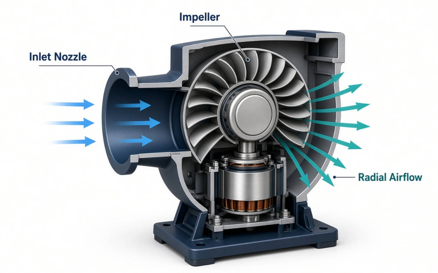
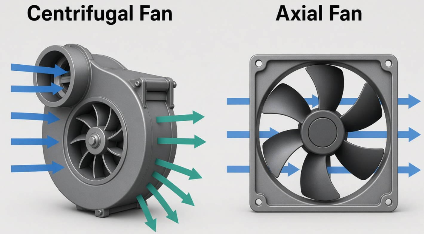
A centrifugal fan draws air toward its rotating impeller and discharges it radially, approximately perpendicular to the inlet direction. An axial fan instead moves air primarily along its rotational axis.
This difference changes how the fan integrates into an enclosure. A centrifugal configuration can suit equipment that requires a turn in the airflow path or pressure capability to move air through restrictive components.
However, centrifugal describes an airflow configuration, not a power supply. DC and AC describe electrical supply categories. Do not treat these terms as competing classifications.
An inlet nozzle guides air into the impeller. Its shape and position affect how smoothly air enters the fan and how closely the installed assembly reproduces the manufacturer's tested performance.
For nozzle-dependent models, evaluate the fan and specified nozzle together. A catalog curve measured with an accessory does not automatically describe the same fan installed without it.
Separating intake and discharge spaces also matters. If discharged air returns directly to the inlet, the fan may circulate air locally instead of delivering useful cooling through the intended path.
Neither design is universally better. Compare candidates at the required airflow and pressure, within your available installation space.
| Selection factor | Centrifugal fan | Axial fan |
|---|---|---|
| Airflow direction | Radial discharge from the impeller | Primarily along the rotational axis |
| Installation focus | Nozzle geometry and discharge clearance | Inlet/outlet clearance and through-flow path |
| Relevant applications | Restrictive passages, dense equipment, heat exchangers | Direct ventilation paths where a suitable model meets resistance |
| Selection evidence | Installed operating point and thermal test | Installed operating point and thermal test |
SANYO DENKI identifies centrifugal fans as suitable for high-density equipment and heat exchangers because of their static-pressure characteristics. That does not mean every centrifugal fan outperforms every axial model.
A high-pressure axial fan may also meet your requirements. Likewise, a poorly integrated centrifugal fan can underperform. The useful comparison is between specific products under equivalent operating conditions.
Airflow describes the volume of air moved over time. Static pressure describes the pressure capability available to overcome resistance in the airflow path.
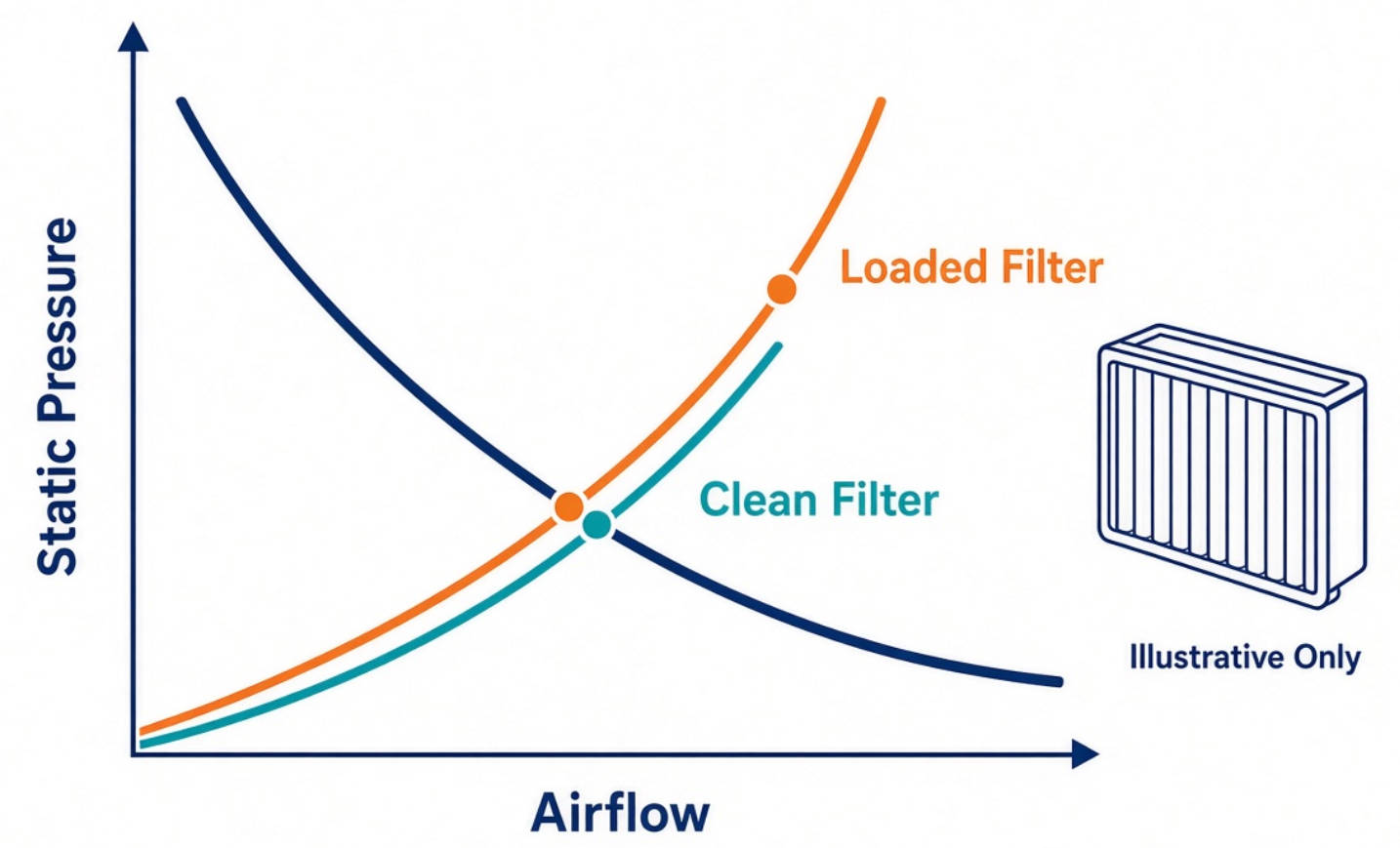
Manufacturers plot these quantities on an airflow–static pressure curve, also called a P–Q curve. Your enclosure has a system-resistance curve showing the pressure required at different airflow rates.
The intersection is the operating point: the airflow and pressure the fan and system achieve together.
Maximum airflow is measured at approximately zero static pressure. Maximum static pressure occurs at approximately zero airflow. These are different endpoints, not simultaneous performance values.
Consequently, a fan advertised with impressive maximum airflow may deliver insufficient air through a dense heat sink or a loaded filter.
Ask for the complete performance curve, not just the two endpoint ratings. Then identify the region corresponding to your equipment's resistance.
The source tutorial describes centrifugal-fan curves with a broader usable operating region than the axial-fan example it presents. Treat that as guidance about the illustrated products, not a universal guarantee for every centrifugal design.
Curve shape, electrical consumption, and noise depend on the specific model and operating condition. Check all three before shortlisting a product.
Record equipment heat dissipation, maximum ambient temperature, allowable component temperatures, and operating modes. Identify local hot spots rather than relying only on an average enclosure temperature.
A bulk-air heat balance can provide an initial airflow estimate, but it cannot reveal bypass flow or uneven cooling. Use it as a starting point, then validate component temperatures in a representative enclosure.
Document every significant restriction:
- Intake grilles and protective guards.
- Clean and partially loaded filters.
- Heat sinks and heat exchangers.
- Duct bends, narrow passages, and cable bundles.
- Exhaust openings and potential recirculation paths.
Include realistic assembly tolerances. A prototype with neatly routed cables may not represent production equipment.
Measure system resistance where practical, or develop an engineering estimate for preliminary selection. Match the desired airflow to the associated pressure requirement.
Document assumptions and uncertainty. Selection margin should address known risks, such as filter loading or supply variation, rather than an arbitrary percentage applied to catalog airflow.
Confirm dimensions, mounting points, nozzle requirements, connector pinout, supply range, and operating temperature. For controlled models, verify the PWM interface and any speed-feedback or alarm functions against the exact datasheet.
Do not assume that every DC fan supports speed control or that every PWM input uses the same electrical specification.
Test temperatures, airflow where measurable, electrical consumption, and acoustics in the intended enclosure. Include worst-case ambient conditions and representative operating loads.
Where relevant, repeat testing with simulated filter loading and fault conditions. Establish pass/fail criteria before testing, and retain results with the selected part number and assembly configuration.
AMCA describes system effect as performance loss associated with adverse flow conditions near a fan. Common causes include obstructions, nonuniform inlet flow, swirl, and unsuitable duct arrangements.
For compact equipment, translate that principle into three practical checks.
Avoid placing a wall, cable bundle, or abrupt transition immediately against the inlet. Use the manufacturer's installation guidance rather than copying clearance rules from an unrelated fan size or configuration.
Check whether mounting brackets, partitions, or nearby components obstruct discharge. Provide a route that directs air through the intended cooling region instead of creating a short recirculation loop.
A fan tested alone is not an enclosure test. Evaluate the final nozzle, guards, seals, ducts, and mounting structure together.
The engineering priority is to remove unnecessary restriction before increasing speed. Higher speed may recover some airflow, but the resulting power and acoustic tradeoffs require measurement.
PWM-compatible centrifugal fans allow external speed control. SANYO DENKI explains that appropriate speed control can reduce system power consumption and noise when full cooling output is unnecessary.
The important word is compatible. Verify control frequency, signal requirements, minimum operating behavior, and the response at zero duty cycle for your selected model.
A documented example is the San Ace C70 9TD centrifugal fan: its technical report specifies a 12 V model, a PWM control function, and a dedicated inlet nozzle. The report also provides curves at several duty cycles.
These details illustrate what a procurement-ready specification should include; they are not specifications for all centrifugal fans.
For temperature-based control, place the sensor where it represents the component risk. Validate start-up, changing loads, sensor faults, and recovery behavior. Avoid allowing a quiet operating mode to conceal an overheating component.
A long-life claim is meaningful only when its test conditions are clear. L10 life indicates a duration at which 90% of the evaluated population is expected to remain operational under the stated conditions.
Check the associated temperature, voltage, and operating environment. SANYO DENKI also defines a rotational-speed threshold for its fan-life assessment, so understand the manufacturer's criterion rather than assuming every supplier uses identical terminology.
Do not translate a catalog life rating into an unconditional equipment warranty. Actual service conditions, contamination, installation, and maintenance requirements still need evaluation.
For sourcing, request the exact datasheet and confirm whether the quoted life applies to your chosen part number. Preserve revision information so replacement purchasing does not silently change the approved specification.
Consider a hypothetical communications enclosure containing heat-generating boards, a filter, and restricted exhaust openings. This is an engineering example, not a documented customer case.

Selecting by free-air airflow alone could overlook the pressure needed to move air through the assembled enclosure. An appropriate evaluation would compare centrifugal and high-pressure axial candidates at the required operating point.
The test plan should examine:
1. Component temperatures at the highest specified ambient condition.
2. Performance with a clean filter and representative filter loading.
3. Intake-to-exhaust recirculation and bypass around hot components.
4. Noise and power at normal and maximum cooling demand.
5. Alarm behavior or system response when cooling is impaired.
The winning candidate is the one that meets these requirements reliably—not necessarily the one with the highest catalog airflow.
Capital Technology Co., Limited supplies cooling solutions through its CAPITAL brand and SANYO DENKI offering. To begin a technically useful product discussion, provide your available space, supply voltage, heat load, ambient range, target airflow and pressure, noise limit, and anticipated annual volume.
If system resistance is unknown, share enclosure drawings and available test information. Request candidate datasheets, accessory requirements, and sample evaluation details before committing to a production selection.
Choose a centrifugal fan through a documented engineering comparison, then verify its performance in your equipment.
It moves air radially and is worth evaluating for restrictive cooling paths, dense equipment, and heat exchangers. Suitability depends on the required operating point and installation.
No. Compare specific models at equivalent airflow and pressure, then measure the installed assembly. Speed, airflow disturbance, mounting, and operating conditions affect the result.
No. They describe opposite endpoints of the performance curve. Actual operation occurs where the fan curve intersects the system-resistance curve.
Check the selected model. If its published performance requires a specified nozzle, evaluate that assembly and follow the manufacturer's mounting guidance.
Yes, for compatible models when reduced speed still meets thermal requirements. Confirm interface specifications and validate the temperature-control strategy under real operating conditions.
Provide dimensions, voltage, heat load, ambient temperature, airflow and pressure targets, noise limits, filter conditions, and required control functions. Drawings and prototype measurements improve the evaluation.
1. SANYO DENKI, "Features of Centrifugal Fan," Tech Compass. Original article supplied for reconstruction. Supports the explanation of radial discharge, inlet nozzles, intake/exhaust separation, and the model-dependent relationship between performance, noise, and power. Supervised by SANYO DENKI's Cooling System Design Department. [techcompass.sanyodenki]
2. SANYO DENKI, "Fan Air Volume and Static Pressure," Tech Compass. Supports the relationship between the fan performance curve, system resistance, and the installed operating point. [techcompass.sanyodenki]
3. AMCA International, "Fan and System Curves with Fan Energy Index." Technical presentation explaining fan curves, system curves, and their intersection as the duty or operating point. [amca]
4. AMCA International, "Mitigating System Effect to Optimize Fan Performance and Efficiency," June 4, 2024. Supports the discussion of adverse inlet/outlet conditions, obstructions, airflow disturbance, and installation-related performance losses. [amca]
5. SANYO DENKI, "ø70 × 20 mm Centrifugal Fan San Ace C70 9TD Type." Technical report supporting the specific 12 V product example, PWM functionality, performance curves at different duty cycles, and dedicated inlet-nozzle requirements. [sanyodenki]
6. SANYO DENKI, "Centrifugal Fan," San Ace product site. Supports application positioning for dense equipment and heat exchangers, and the potential benefits of speed control on PWM-compatible models. [products.sanyodenki]
7. SANYO DENKI, "Fan Lifespan," Tech Compass. Supports the L10 explanation, temperature-dependent life evaluation, the manufacturer's rotational-speed life criterion, and the distinction between maximum airflow and maximum static pressure. [techcompass.sanyodenki]
8. Capital Technology Co., Limited, company brief supplied in this request. Basis for the CAPITAL brand and company product positioning. No public supporting page or customer-review material was provided.


