From idea to market-ready product, our NPI solutions make every stage easier, faster. Discover How We Help
Help Center

Views: 226 Author: Capital Technology Publish Time: 2026-10-23 Origin: Site
Content Menu
● What Is a Blower Fan, and How Does It Work?
● Blower Fan vs. Axial Fan: Which Fits Your Cooling System?
● Why Static Pressure Matters More Than Maximum Airflow Alone
● How to Estimate Required Cooling Airflow
>> Start With Heat Dissipation and Allowable Temperature Rise
>> Worked Example: A 200 W Electronics Assembly
● A Practical Six-Step Blower Fan Selection Process
>> 1. Define the Thermal and Mechanical Requirements
>> 2. Establish System Resistance
>> 3. Compare Curves at the Required Operating Point
>> 4. Confirm Electrical Compatibility
>> 5. Check Environmental and Reliability Requirements
>> 6. Validate the Complete Equipment
● Installation Details That Can Undermine Blower Performance
>> Connect the Outlet to the Intended Cooling Path
>> Prevent Hot-Air Recirculation
● How to Reduce Blower Fan Noise and Power Consumption
● Application Example: Cooling a Compact Telecom Enclosure
● What to Send Your Blower Fan Supplier
● Discuss Your Cooling Requirements With Capital Technology
>> 1. What Is the Main Advantage of a Blower Fan?
>> 2. Is a Blower Fan Always Better Than an Axial Fan?
>> 3. Can I Select a Blower Using CFM Alone?
>> 4. Can a DC Blower Fan Use PWM Speed Control?
>> 5. Why Does a Blower Perform Poorly After Installation?
>> 6. How Can I Reduce Blower Noise Without Losing Cooling?
A blower fan is worth considering when cooling air must pass through dense components, filters, narrow ducts, or restrictive heat sinks. Unlike an axial fan, which moves air mainly along its rotational axis, a centrifugal blower redirects air through a scroll-shaped housing toward a defined outlet. This makes it useful for high-static-pressure cooling and targeted airflow delivery.
At Capital Technology Co., Limited, our approach to DC fan and AC fan selection starts with the equipment—not the largest airflow figure in a catalog. The practical question is whether a fan can deliver enough air through the actual cooling path while meeting temperature, noise, power, and installation requirements.
This guide explains how blower fans work, when they make sense, and how to select and validate one for industrial electronics.
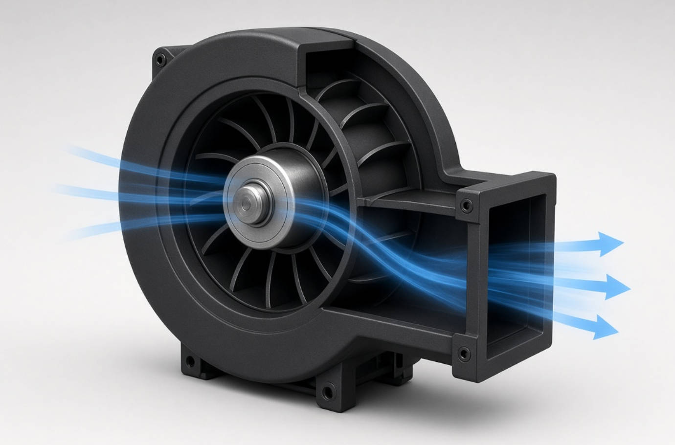
A blower fan uses a rotating impeller to draw air into its inlet and discharge it radially. A surrounding scroll, also called a volute, collects this air and guides it toward an outlet.
The housing is not simply a protective cover. Its geometry helps manage airflow and develop pressure.
Three elements determine the resulting performance:
- Impeller geometry, including blade shape and arrangement.
- Housing and outlet design.
- Motor speed and control characteristics.
In electronics cooling, this configuration is useful when air needs to change direction or reach a specific component through a duct.
However, terminology varies between suppliers. A blower is a type of centrifugal fan; "blower fan" and "centrifugal fan" are not universally separate categories. Compare the actual housing, discharge arrangement, and performance curve rather than relying on the product name.
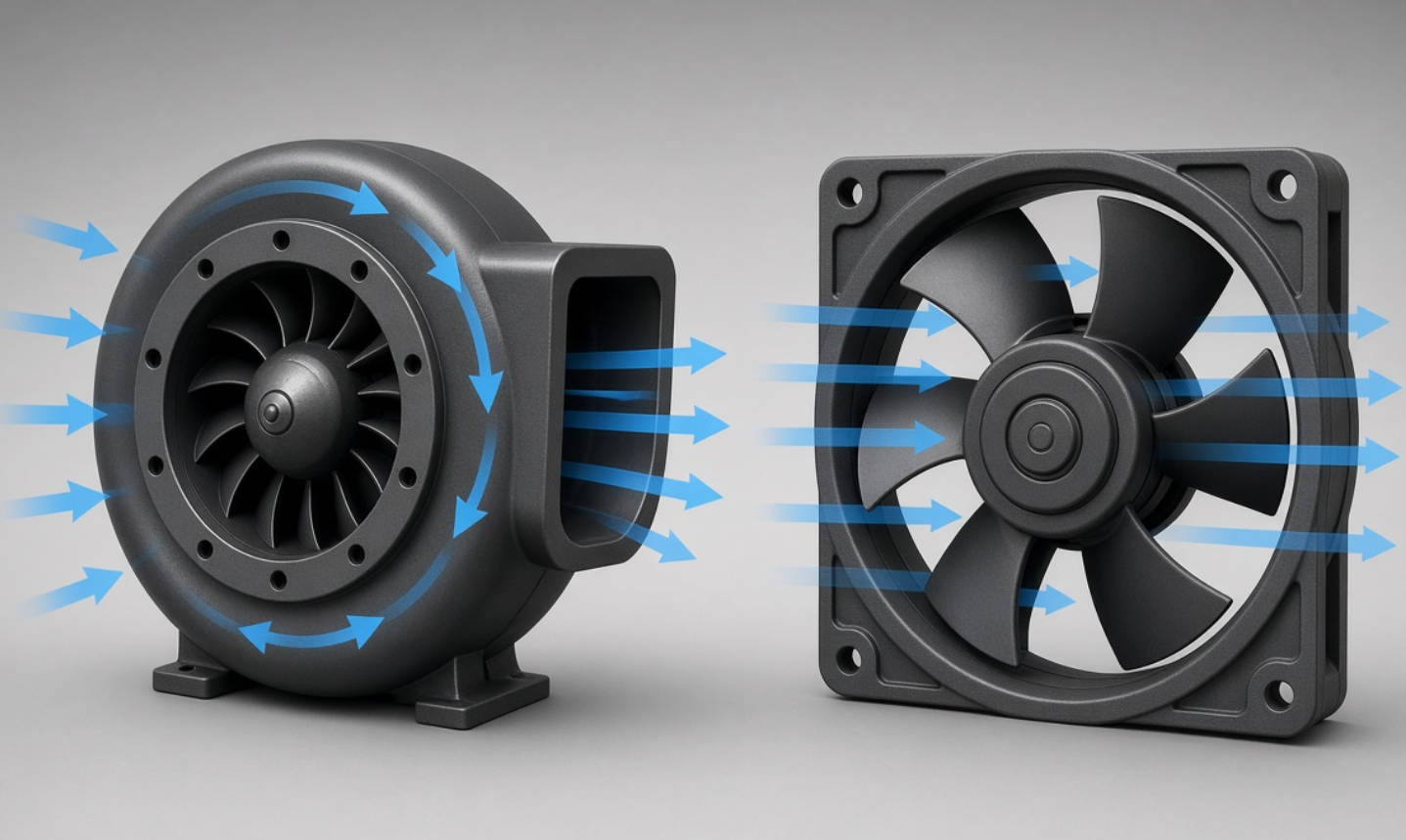
Neither design is automatically better. The right choice depends on the airflow path and the resistance it creates.
| Selection factor | Scroll-housed blower fan | Axial cooling fan |
|---|---|---|
| Airflow direction | Inlet and discharge are typically perpendicular | Air moves mainly along the rotational axis |
| Common strength | Pressure capability and directed discharge | High airflow through relatively open paths |
| Installation considerations | Requires space for the housing and outlet connection | Often suits direct panel mounting |
| Typical applications | Ducts, restrictive heat sinks, localized cooling | Enclosure ventilation and general air exchange |
| Selection priority | Airflow delivered against system resistance | The same requirement—not free-air airflow alone |
A blower can be particularly useful when a single outlet must direct air into a narrow cooling channel.
An axial fan may be more practical when a cabinet has generous ventilation openings and a relatively unobstructed air path.
These are tendencies, not performance guarantees. High-static-pressure axial designs also exist, so compare suitable models at the same required operating point.
Maximum airflow describes performance under approximately zero external static pressure. Maximum static pressure describes the opposite endpoint: pressure capability at approximately zero airflow.
A fan does not deliver both maximum values simultaneously.
Inside real equipment, air encounters resistance from:
- Filters and protective grilles.
- Heat-sink fins.
- Circuit boards and wiring.
- Duct bends and transitions.
- Small inlet or exhaust openings.
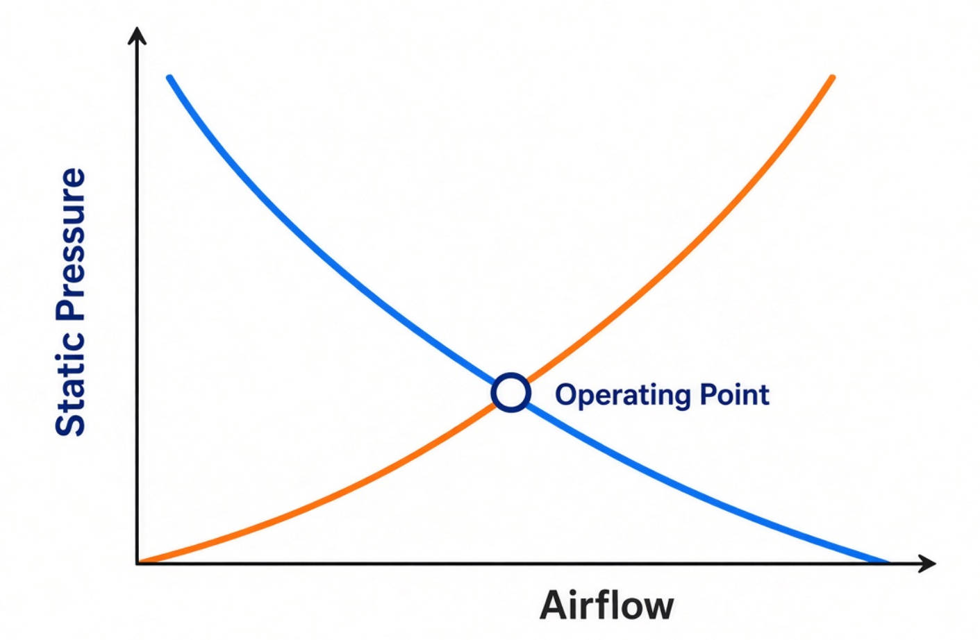
The actual airflow is determined by the intersection of the fan's pressure–airflow curve and the system resistance curve. This intersection is the operating point.
For purchasing decisions, this distinction is critical. A blower with a lower maximum airflow rating may deliver more useful cooling air through a restrictive assembly than another fan with a higher free-air rating.
Ask for the complete performance curve, not just a specification table.
Before choosing a blower, estimate how much heat the air must remove.
For an initial steady-state calculation:
V˙=P/ρcpΔT
Where:
- V˙ is volumetric airflow in m³/s.
- P is heat transferred to the cooling air in watts.
- ρ is air density in kg/m³.
- cp is air's specific heat capacity in J/(kg·K).
- ΔT is the permitted air temperature rise in °C or K.
Use actual heat dissipation rather than automatically treating total equipment input power as waste heat.
Assume an assembly transfers 200 W into its cooling air and permits a 10°C air temperature rise.
Using approximate room-condition values of 1.2 kg/m³ for air density and 1,005 J/(kg·K) for specific heat:
V˙=200/(1.2×1,005×10)≈0.0166 m³/s
This equals approximately 35 CFM.
That figure is a preliminary requirement for delivered airflow—not a recommendation to purchase a blower rated at 35 CFM maximum.
The selected unit must supply the required airflow against the enclosure's resistance. Hotspots, leakage, recirculation, altitude, and heat transferred through other paths also affect the final design.
Record heat dissipation, maximum ambient temperature, component temperature limits, available dimensions, and inlet and outlet locations.
Identify whether the objective is whole-enclosure ventilation or cooling a specific heat source. The answer changes the airflow layout.
Include the complete airflow path: inlet grille, filter, heat sink, duct, internal obstructions, and exhaust.
Where possible, measure resistance in a representative assembly. If it is estimated, document the assumptions and verify them during prototype testing.
For filtered equipment, consider both clean-filter and service-condition resistance.
Evaluate candidate blowers at the required airflow and pressure together.
Check the exact model, supply voltage, speed setting, and test conditions behind each curve. Similar dimensions do not guarantee equivalent installed performance.
Avoid selecting a universal airflow multiplier as a substitute for understanding system resistance.
For a DC blower fan, review:
- Rated voltage and permitted operating range.
- Running and startup current.
- Connector pinout and polarity.
- PWM control requirements, if available.
- Speed feedback or alarm functions, if available.
For an AC-powered option, confirm rated voltage, frequency, wiring, and applicable safety requirements.
Control and monitoring functions are model-specific. Do not assume every blower supports the same interface.
Review operating temperature, humidity, dust exposure, vibration, mounting orientation, and expected service conditions.
Compare life ratings only alongside their stated temperature and test conditions. Also check whether environmental protection applies to the complete assembly or only particular components.
Test the blower in its intended enclosure with production-representative filters, ducts, covers, cables, and grilles.
Measure critical component temperatures, inlet temperature, electrical consumption, and noise. Include the highest intended thermal load and ambient conditions.
A catalog curve supports selection; equipment-level testing establishes suitability.
A nearby panel or cable bundle can obstruct the inlet and create uneven inflow.
Provide clearance appropriate to the selected blower and confirm its effect experimentally. A successful open-bench test does not prove the same performance inside a crowded housing.
A blower's directed discharge is useful only if the air reaches the target.
Poorly fitted ducts, leakage gaps, and abrupt transitions can waste pressure or allow air to bypass a heat sink. Consider seals and airflow guides where appropriate, while avoiding unnecessary restrictions.
Separate intake and exhaust paths sufficiently to prevent heated discharge air from returning to the inlet.
During testing, measure the temperature entering the blower. Room temperature alone may conceal a recirculation problem inside or around the equipment.
Start by reducing unnecessary airflow resistance. A larger vent, better cable routing, or smoother duct transition may reduce the pressure required for cooling.
Where supported, PWM control allows blower speed to respond to thermal demand rather than remaining at full speed continuously.
A practical control strategy should:
1. Monitor a temperature relevant to the protected component.
2. Maintain sufficient cooling at low load.
3. Increase speed before temperature limits are reached.
4. Define a response to fan or sensor faults.
The source training material describes a blower example whose sound pressure level is lowest around the middle of its performance range. Treat this as a useful design insight, not a universal guarantee.
Noise depends on the model, operating point, mounting, airflow path, and measurement conditions. Verify it in the finished equipment.
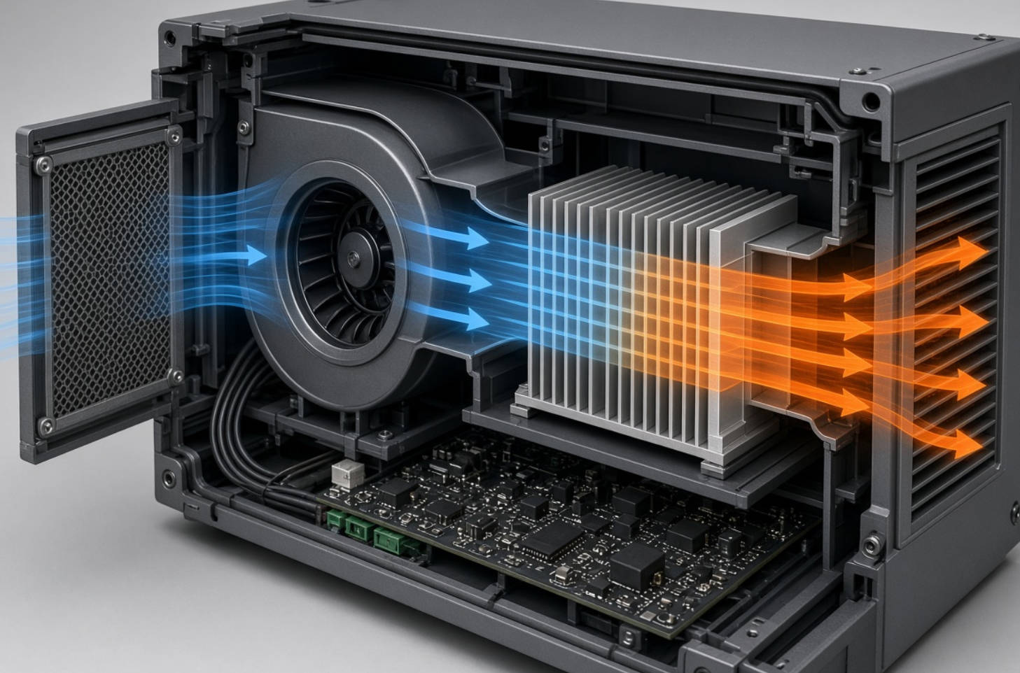
Consider a hypothetical telecom enclosure containing dense electronics, a filtered inlet, and a narrow heat-sink channel.
A fan selected only by free-air CFM could disappoint because the filter and heat sink create substantial resistance.
A disciplined evaluation would:
- Estimate the required heat-removal airflow.
- Establish the pressure loss through the complete path.
- Compare blower and high-pressure axial candidates.
- Guide air through the heat sink rather than around it.
- Test clean and representative service-condition filters.
- Validate temperatures and noise across the intended operating range.
This is an illustrative engineering scenario, not a reported customer installation. Its lesson applies broadly: improve the airflow path before assuming a faster fan is the only solution.
A clear technical inquiry helps suppliers identify suitable products and reduces comparison errors.
| Information to provide | Why it matters |
|---|---|
| Heat dissipation and temperature limits | Establishes the cooling objective |
| Required airflow and estimated pressure | Defines the target operating point |
| Available dimensions and airflow direction | Determines mechanical compatibility |
| Supply voltage and control needs | Establishes electrical compatibility |
| Ambient conditions and contamination | Guides environmental selection |
| Noise target and measurement conditions | Makes acoustic comparisons meaningful |
| Prototype quantity and production demand | Supports sampling and supply planning |
Request the exact model datasheet, performance curve, electrical details, dimensional drawing, and relevant compliance documentation.
Capital Technology Co., Limited supplies DC fan and AC fan cooling solutions through its CAPITAL brand and SANYO DENKI product offering.
According to the company information supplied for this article, Capital is a chief agent for SANYO DENKI and has supplied ZTE, HUAWEI, and HYTERA. These relationships provide company background; they do not replace application-specific technical validation.
Send Capital your enclosure drawing, heat load, available voltage, target airflow and pressure, and noise requirements. Request a model comparison and sample-evaluation plan based on your actual operating conditions.
A scroll-housed blower can develop useful pressure and direct air through a defined outlet. This makes it suitable for restrictive cooling paths and targeted airflow delivery.
No. An axial fan may suit open ventilation paths better. Compare both designs at the airflow and pressure your equipment requires, including installation space and noise constraints.
No. Maximum CFM normally describes free-air performance. Selection requires checking delivered airflow at the system's resistance using the pressure–airflow curve.
Some models can. Confirm the specified signal frequency, voltage levels, duty-cycle range, minimum-speed behavior, and wiring before designing the controller.
Common causes include blocked inlets, restrictive outlets, filter pressure loss, leakage, recirculation, and incorrect electrical supply. Test the complete assembly rather than the blower alone.
Reduce avoidable resistance, improve airflow routing, prevent vibration transmission, and use appropriate speed control. Confirm component temperatures after every change.
1. [SANYO DENKI — "Blower Fan Features," Fan Basics, Lesson 11]. Primary source for blower structure, directed discharge, pressure–airflow characteristics, and the described power and acoustic tendencies. Supervised by the Cooling System Design Department. [techcompass.sanyodenki]
2. [SANYO DENKI — "Fan Airflow and Static Pressure," Fan Basics, Lesson 4]. Background on airflow, static pressure, rotational speed, and limitations of theoretical combined-fan performance. [techcompass.sanyodenki]
3. [SANYO DENKI — "Basic Knowledge for Selecting a Cooling Fan"]. Guidance on cooling requirements, installation environment, and PWM-based noise management. [techcompass.sanyodenki]
4. [Same Sky — "Understanding Airflow Fundamentals for Proper DC Fan Selection"]. Basis for the heat-balance equation and the distinction between free-air ratings and installed performance. The 200 W example is an illustrative calculation using explicitly stated assumptions. [sameskydevices]
5. [Oriental Motor — "Fan Basics: Air Flow, Static Pressure, and Impedance"]. Supporting explanation of system resistance and the intersection that determines installed airflow. [blog.orientalmotor]
6. [SANYO DENKI — "What Is an Axial Fan? Features, Structure and Usage"]. Supporting information on axial-fan characteristics, applications, and operating-region considerations. [techcompass.sanyodenki]


